Electronic latch mechanism

a latch mechanism and electronic technology, applied in the field of latch mechanisms, can solve the problems of unable to provide power to the electronic lock for a limited period, power supply cannot be used to provide power to the electronic lock, and various components of the electronic lock may cease to opera

Active Publication Date: 2011-03-10
COMPX INTERNATIONAL
View PDF19 Cites 61 Cited by
  • Summary
  • Abstract
  • Description
  • Claims
  • Application Information

AI Technical Summary

Benefits of technology

[0021]In accordance with yet additional aspects of certain embodiments of the present disclosure, the latch apparatus is designed such that it can provide secure access to both linear enclosure drawer arrangements and arching enclosure door arrangements.
[0022]For example, one embodiment of the present disclosure may be directed to an apparatus for providing secure access to an enclosure. The apparatus may include an actuating device, such as a solenoid, having a locked position and an unlocked position. The apparatus may further include a lever catch operably connected to the actuating device and a latch hook having an open position and a closed position. The lever catch may prevent the latch hook from moving to the open position when the solenoid is in the locked position and the latch hook is in the closed position.

Problems solved by technology

Often times such power supplies, such as in the case of battery power supplies, can only provide power to the electronic lock for a limited period of time before failure.
Once the power supply fails, the power supply will no longer be able to provide power to the electronic lock, and various components of the electronic lock may cease to operate.
To address the limited power resources of many power supplies, electronic locks often times operate in either of an intentional fail safe or fail secure mode.
When the power supply fails, the solenoid or other actuating device will no longer be energized, resulting in the lock being in the unlocked state during a power supply failure.
When the power supply fails, the solenoid or other actuating device will no longer be energized, resulting in the lock being in a locked state during a power supply failure.
Moreover, certain electronic locks may require a significant amount of energy to operate the solenoid or other actuating device, resulting in a significant drain on available and often limited power resources.
Other electronic locks can be bulky and not desirable for providing secure storage to enclosures such as furniture drawers.
While various implementations of latching mechanisms have been developed, no design has emerged that generally encompasses all of the desired characteristics as hereafter presented in accordance with the subject technology.

Method used


Image

  • Electronic latch mechanism
  • Electronic latch mechanism
  • Electronic latch mechanism

Examples


Embodiment Construction

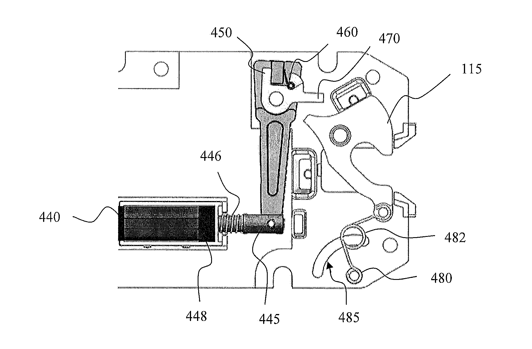
[0052]As discussed in the Summary of the Invention section, the present subject matter is concerned with a latch apparatus.

[0053]Selected combinations of aspects of the disclosed technology correspond to a plurality of different embodiments of the present disclosure. It should be noted that each of the exemplary embodiments presented and discussed herein should not insinuate limitations of the present subject matter. Features or steps illustrated or described as part of one embodiment may be used in combination with aspects of another embodiment to yield yet further embodiments. Additionally, certain features may be interchanged with similar devices or features not expressly mentioned which perform the same or similar function.

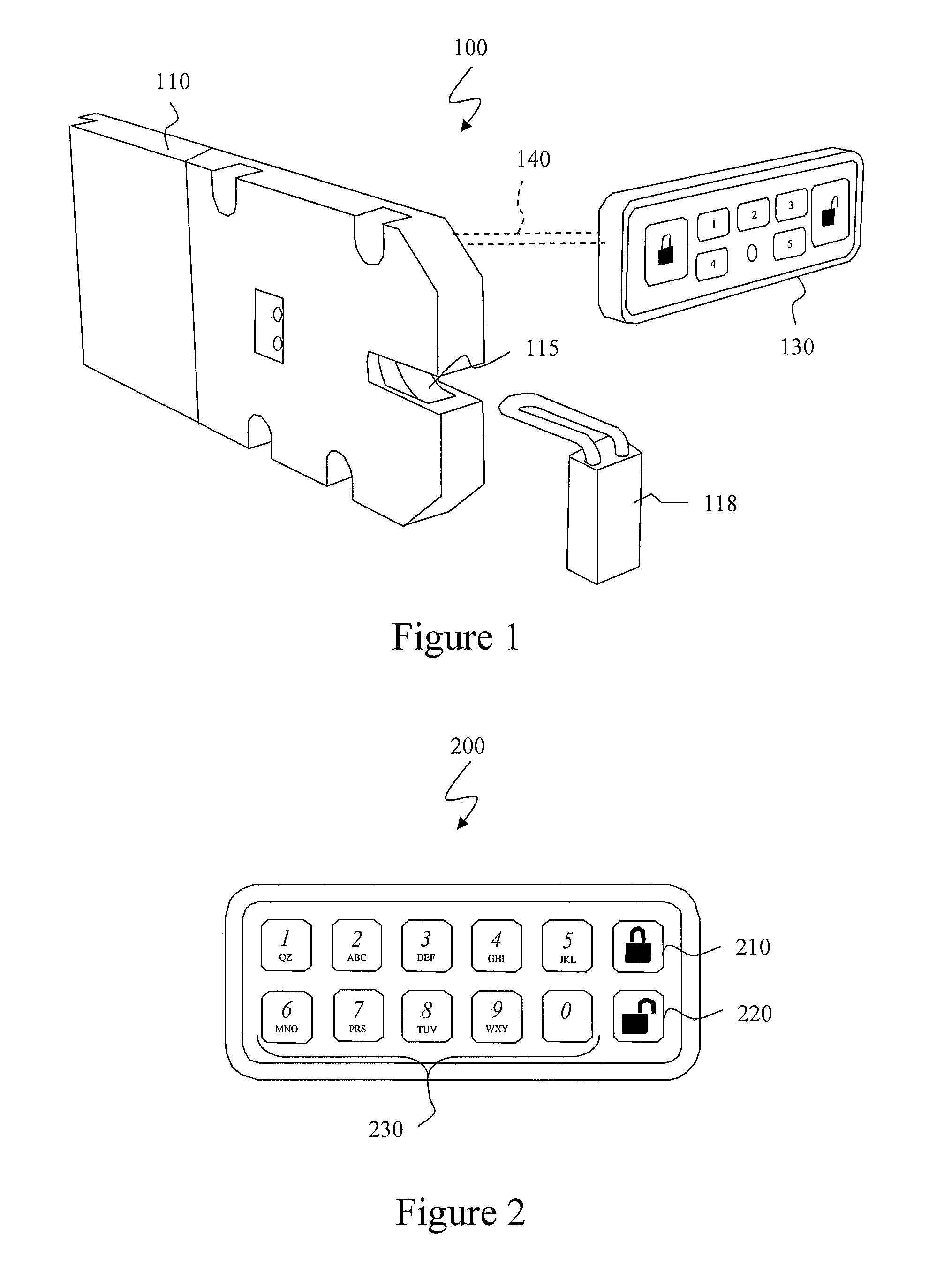
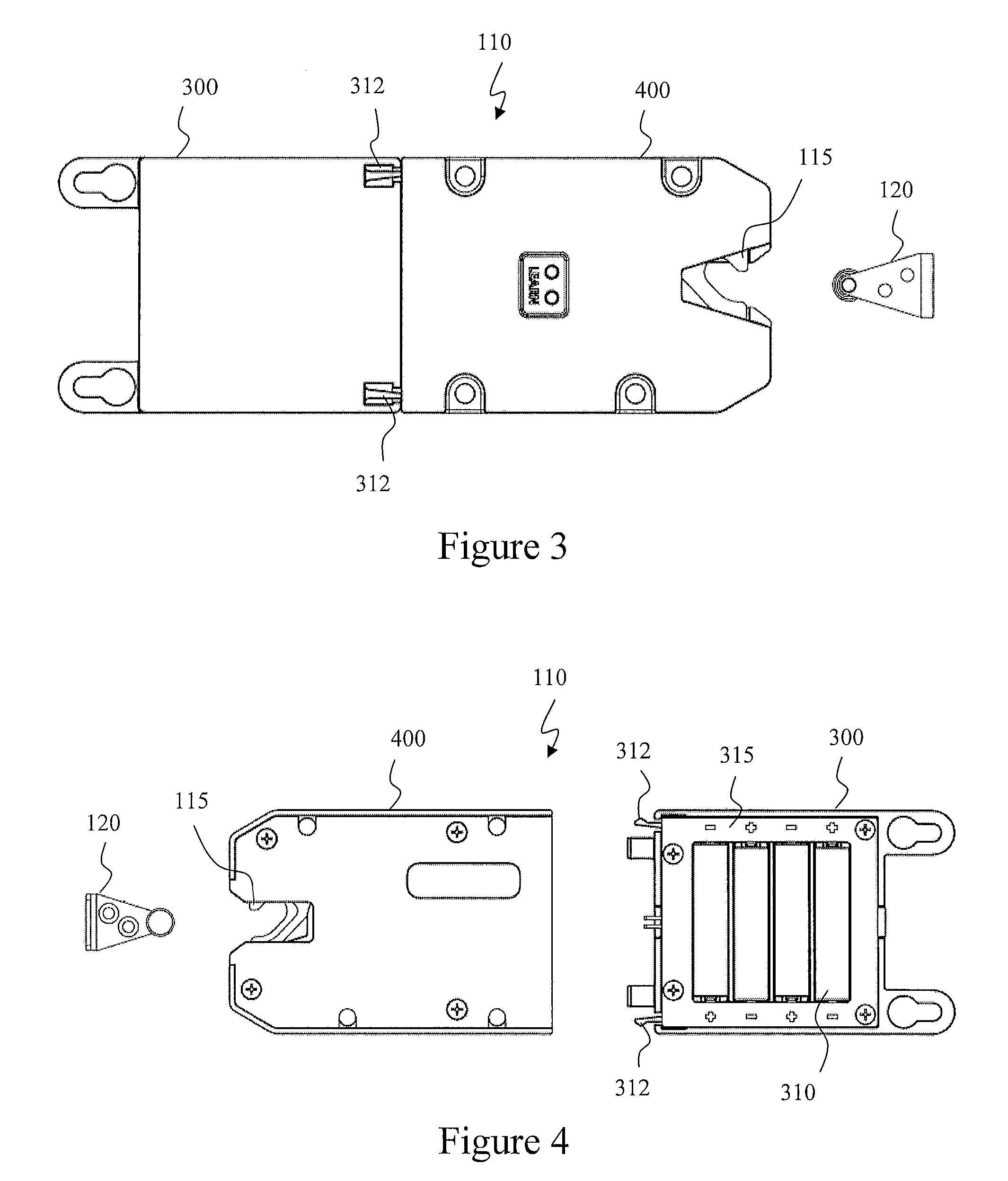
[0054]Generally, the present subject matter is directed to a latch apparatus that can be used to provide secure storage to an enclosure. The latch apparatus may be configured to be operated remotely from a control pad or other remote device. For instance, the ...


PUM


Abstract

A latch apparatus for providing secure storage to an enclosure is disclosed. The latch apparatus can include an actuating device that operates to lock or unlock the latch apparatus in response to a control signal. The control signal can be communicated to the latch apparatus through an RF or other transmitted signal or through hardwires connecting the latch apparatus to the remote device. The latch apparatus can be maintained in either a locked state or an unlocked state without having to continuously supply power to the latch apparatus. The latch apparatus can include a latch hook that can be detent biased to both the open position and the closed position while the latch apparatus is in either a locked state or an unlocked state. The latch hook can move from the open position to the closed position while the latch apparatus is in a locked state. The latch apparatus can also have a thickness such that the latch apparatus will fit in the gap in which drawer slide hardware for an enclosure is installed.

Description

PRIORITY CLAIM[0001]This application claims the benefit of previously filed U.S. Provisional Patent Application entitled “ELECTRONIC LATCH MECHANISM,” assigned U.S. Ser. No. 61 / 241,067, filed Sep. 10, 2009, and which is incorporated herein by reference for all purposes.FIELD OF THE INVENTION[0002]The present subject matter generally relates to latch mechanisms. More specifically, the present subject matter relates to an electronic latch apparatus that may have the capability of being remotely locked and unlocked through an RF or other control signal.BACKGROUND OF THE INVENTION[0003]Many occasions arise that require the use of latching mechanisms to control access to different types of cabinets, entryway doors, carts, furniture, tool boxes, and other types of boxes, hereafter collectively referred to as enclosures, regardless generally of their compositions, materials, or configurations. Such enclosures may be provided with doors and / or may also include drawers.[0004]Electronic locks...

Claims


Application Information

Patent Timeline
Patent Type & Authority Applications(United States)
IPC IPC(8): E05B65/46E05B47/02
CPCB62B3/1404E05B47/0002E05C3/24E05B47/0607E05B2047/0094E05B47/0004Y10T70/7102Y10T70/5128Y10T70/7062Y10T292/1082Y10T70/70Y10T70/5978
Inventor GREINER, MATTHEW R.WALLA, GREGG W.
Owner COMPX INTERNATIONAL
Why Eureka
Try Eureka