Vent Opening Mechanism

a technology of opening mechanism and canning lid, which is applied in the direction of transportation and packaging, other domestic articles, liquid handling, etc., can solve the problems of reducing the flow rate of the fluid flowing out of the can, user spilling the fluid on himself/herself, and causing the fluid to flow turbulently, so as to prevent sharp edges

Inactive Publication Date: 2011-03-10
EMANUELE ARTHUR JOSEPH III
View PDF20 Cites 71 Cited by
  • Summary
  • Abstract
  • Description
  • Claims
  • Application Information

AI Technical Summary

Benefits of technology

[0015]The method may further comprise the step of limiting the movement of the vent opening portion

Problems solved by technology

Unfortunately, during the pouring process, the fluid within the can blocks the entire opening through which the fluid is being poured out of.
As a result, air must enter the drink can through such opening and may cause the fluid exiting the can to have a turbulent flow.
Such turbulent flow ma

Method used


Image

  • Vent Opening Mechanism
  • Vent Opening Mechanism
  • Vent Opening Mechanism

Examples


Embodiment Construction

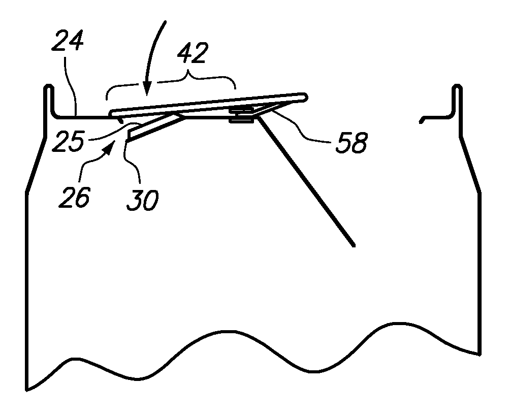
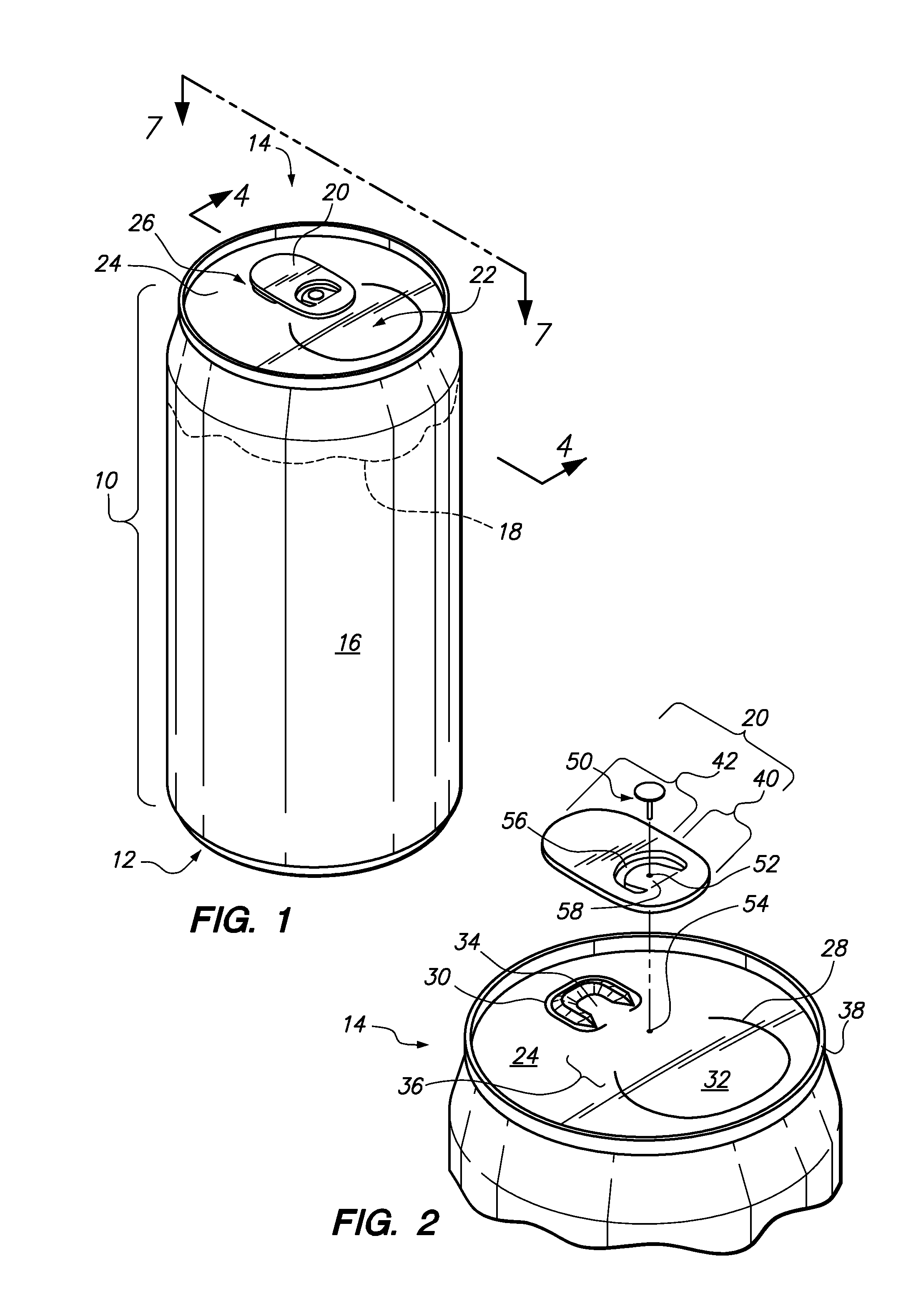
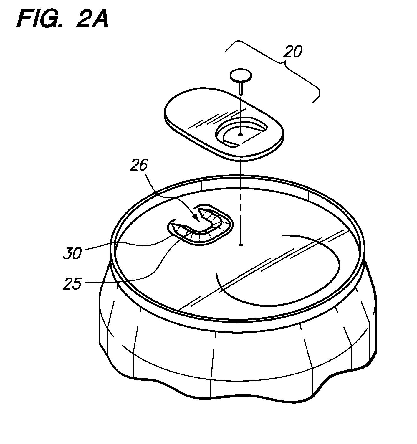
[0036]Referring now to the drawings, FIG. 1 illustrates a can 10 used to hold fluid 18. The can 10 defines a bottom end 12, a top end 14 and a sidewall 16. The top end and bottom ends 14, 12 may be attached to the opposed ends of the sidewall 16 to form a container to hold fluid 18. The can 10 may provide a fluid tight container so that the fluid 18 does not escape from the can 10 during transportation and prior to use. During use, the user may flip up a tab 20 to open drinking opening 22 (see FIG. 5) so that the fluid 18 may be poured out of the can 10 (see FIG. 3). The tab 20 may then be flipped back downward and pushed toward an upper panel 24 of the top end 16 to open the vent opening 26 (see FIG. 6) so that fluid 18 may flow smoothly out of drink opening 22 when poured (see FIG. 3). When the tab 20 is flipped back downward and pushed toward the upper panel 24 of the top end 16, the tab 20 pushes upon the ridge 25 disposed closely to a score line 30 defining the vent opening 26....


PUM


Abstract

An improved drink can is disclosed wherein the drink can has a drink opening and a vent opening which are positioned opposite from each other with respect to a central portion of a top end of a drink can. The tab is attached to the central portion and can be pulled upward to open the drink opening then pushed back downward to open the vent opening. To aid in opening the vent opening with the tab, the vent opening may have a ridge to provide additional leverage when the tab pushes downward on a score line that defines the vent opening. The tab may be enlarged so that upon breakage of the score line to the vent opening, the tab contacts the top end of the can and does not allow the user's finger to proceed into the vent opening and possibly cut the user's finger.

Description

CROSS-REFERENCE TO RELATED APPLICATIONS[0001]This application claims the benefits of U.S. Prov. Pat. App. Ser. No. 61 / 276,373 filed on Sep. 10, 2009, the entire contents of which is expressly incorporated herein by reference.STATEMENT RE: FEDERALLY SPONSORED RESEARCH / DEVELOPMENT[0002]Not ApplicableBACKGROUND[0003]The present invention relates to an improved drink can.[0004]Fluids such as alcohol, carbonated drinks, etc. may typically be transported from one location to another in a fluid tight can. The can may have an opening for pouring the fluid contained within the can either as the user is drinking the fluid or pouring the fluid into a separate container (e.g., glass). Unfortunately, during the pouring process, the fluid within the can blocks the entire opening through which the fluid is being poured out of. As a result, air must enter the drink can through such opening and may cause the fluid exiting the can to have a turbulent flow. Such turbulent flow may cause the fluid to s...

Claims


Application Information

Patent Timeline
IPC IPC(8): B65D17/32B65D17/34
CPCB65D17/165B65D2517/0014B65D2517/0094B65D17/24B21D51/383B65D17/161B65D41/32B65D17/401B65D17/4012B65D17/404B65B69/00B65D1/165B65D47/32B65D2517/0013
Inventor EMANUELE, III, ARTHUR JOSEPHCHURCH, ROBERT CLARKE
Owner EMANUELE ARTHUR JOSEPH III
Why Eureka
Try Eureka