Fan and method for operating a fan

a fan and fan body technology, applied in the direction of liquid fuel engines, marine propulsion, vessel construction, etc., can solve the problems of increasing material fatigue, reducing the service life of the brush motor, and affecting the vibration of the electric power tool, so as to reduce the moment of the fan, the blade deformation is less, and the flow deflection is less

Inactive Publication Date: 2011-03-10
ROBERT BOSCH GMBH
View PDF14 Cites 5 Cited by
  • Summary
  • Abstract
  • Description
  • Claims
  • Application Information

AI Technical Summary

Benefits of technology

[0018]Because of the lesser blade deformation at the operating point (that is, at a lesser rpm), there are a lesser flow deflection and a lower fan moment, and thus better efficiency of an electric power tool or electrical appliance in which the fan is disposed. As a result of the utilization of the fluid and centrifugal forces, which are always present, additional fittings, such as an active mechanical adjusting mechanism in the electric power tool or electrical appliance, can be dispensed with.
[0019]In the preferred passive variable-rpm blade deformation in preferred radial fans, for regulating the operating performance of electric power tools, an adaptation of the fan characteristic of the radial fan can advantageously be achieved by means of passive blade deformation, utilizing the incident fluid and centrifugal forces for optimizing the operating performance of electric power tools. In a favorable way, in the first alternative, the idling rpm can be reduced, and as a consequence, component vibration can be lessened. This also increases the brush service life in the AC range and postpones fatigue in the material. Noise emissions from the preferred electric power tool can be reduced as well.

Problems solved by technology

Because of sometimes excessive idling rpm because of an overly low fan moment in idling, interfering vibration of the electric power tool can occur or be increased, which among other things reduces the brush service life of the electric motor and contributes to increased material fatigue.
At the same time, noise emissions and the vibration load on the component structure both increase because of the high rpm.

Method used


Image

  • Fan and method for operating a fan
  • Fan and method for operating a fan
  • Fan and method for operating a fan

Examples


Embodiment Construction

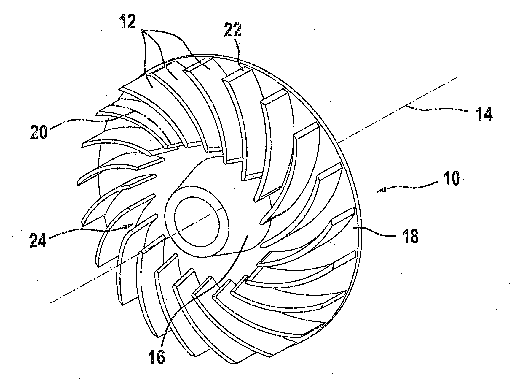
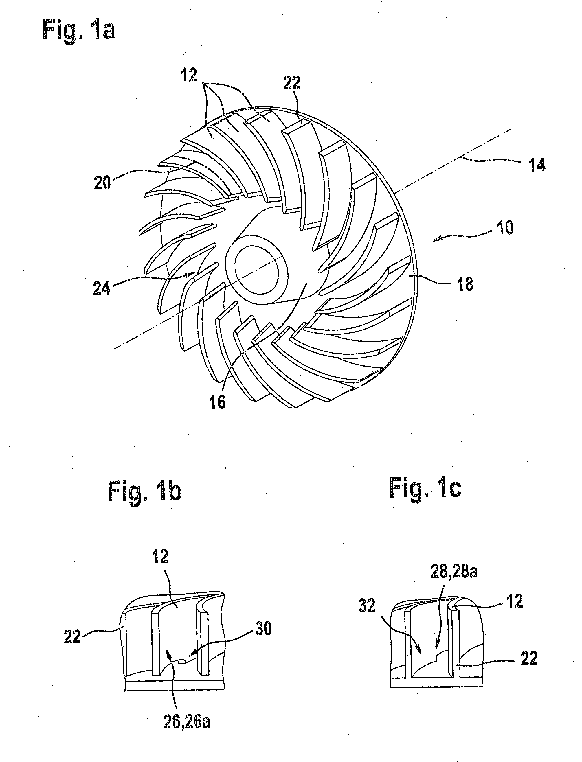
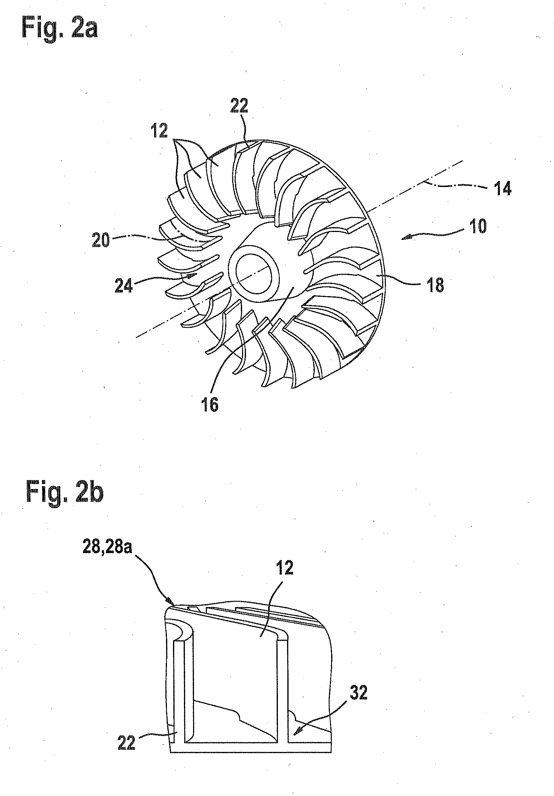
[0033]In the drawings, functionally identical or identically acting elements are each identified by the same reference numerals. The figures are schematic illustrations of the invention. They do not show specific parameters of the invention. Furthermore, the figures show only typical features of the invention and are not intended to limit the invention to the features shown.

[0034]For explaining the invention, FIGS. 1a-1c and 2a, 2b show a fan 10 with a fan hub 18. A plurality of fan blades 12 for deflecting an air flow is disposed on the fan hub 18 about a rotational axis 14. The inflow direction of the air flow is in the axial direction in the center region 16 of the fan hub 18. A shaft, not shown, is disposed at the center of the center region 16. For the sake of simplicity, no cover disk is shown, since it would conceal the fan blades 12. However, it is understood that it can be present and can be connected to the fan blades 12 in a way comparable to what is described below for t...


PUM


Abstract

The invention relates to a fan, particularly a radial fan, having a fan hub with a rotational axis. A plurality of fan blades is disposed about the rotational axis for deflecting an air flow. The invention provides that an adjustment device is provided at the fan blades for the rotational speed-dependant adjustment of an air flow.

Description

PRIOR ART[0001]The invention is based on a fan and a method for operating a fan as generically defined by the preambles to the independent claims.[0002]It is generally known in electric power tools to use fans, especially radial and semiaxial fans. Because of sometimes excessive idling rpm because of an overly low fan moment in idling, interfering vibration of the electric power tool can occur or be increased, which among other things reduces the brush service life of the electric motor and contributes to increased material fatigue.[0003]The fan in an electric power tool performs the task first of cooling the thermally stressed components in the electric power tool, and second, of regulating the idling rpm of the motor by means of a suitable idling moment. In a universal motor, for instance, by means of a fan disposed on the armature shaft, the universal motor is protected against uncontrolled revving during idling. A low load moment is also created by supporting the armature shaft ...

Claims


Application Information

Patent Timeline
Patent Type & Authority Applications(United States)
IPC IPC(8): F04D29/36
CPCF04D29/305F04D29/282
Inventor SADIKOVIC, ADAMORICHL, STEFANALTVATER, BERND
Owner ROBERT BOSCH GMBH
Why Eureka
Try Eureka