Armor systems

a technology of armor system and armor shield, which is applied in the direction of protective fabrics, braids, weaving, etc., can solve the problems of affecting the performance of armor shields, etc., and achieves the effect of higher performan

Inactive Publication Date: 2005-09-20
HONEYWELL INT INC
View PDF21 Cites 21 Cited by
  • Summary
  • Abstract
  • Description
  • Claims
  • Application Information

AI Technical Summary

Benefits of technology

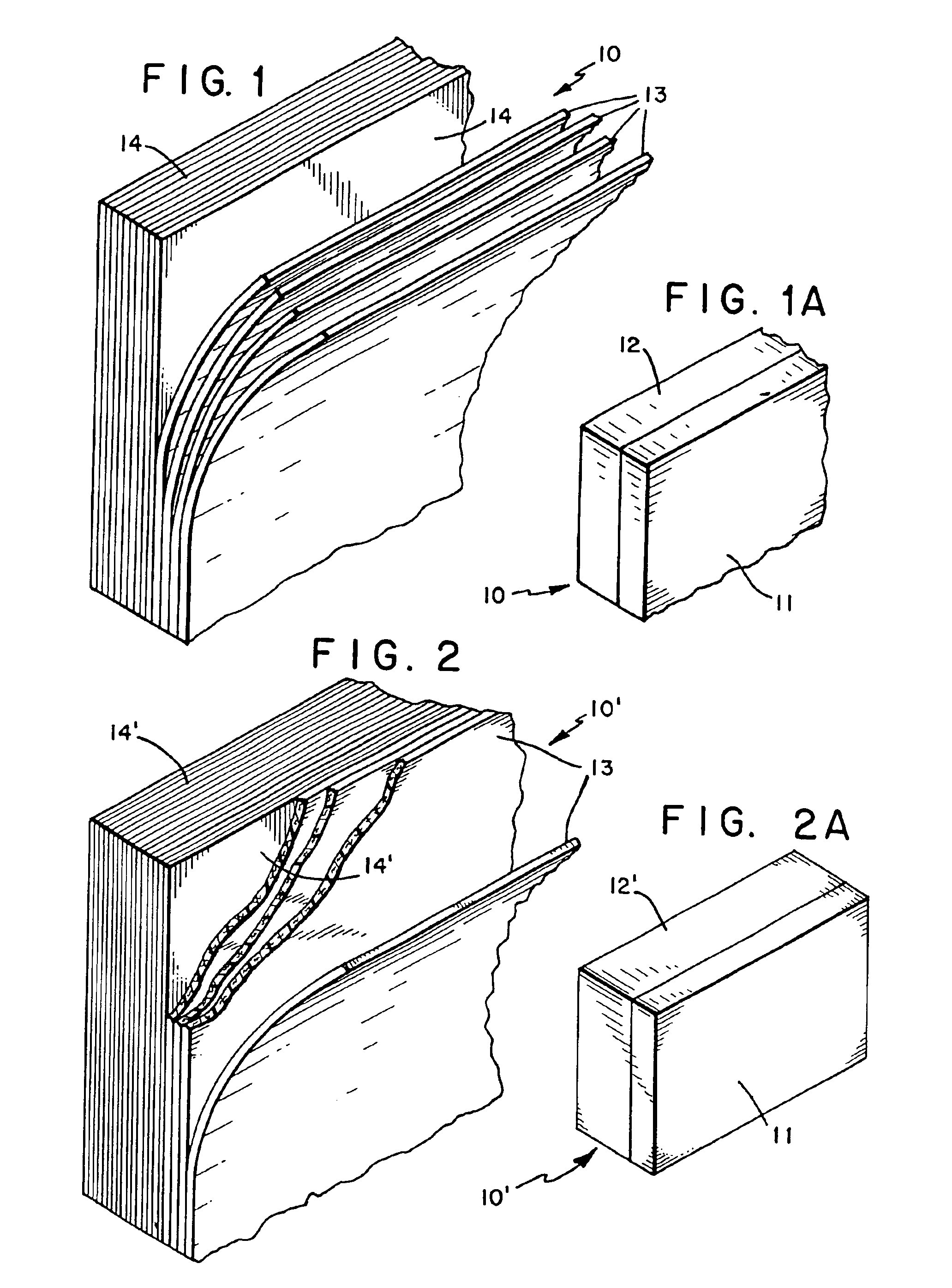
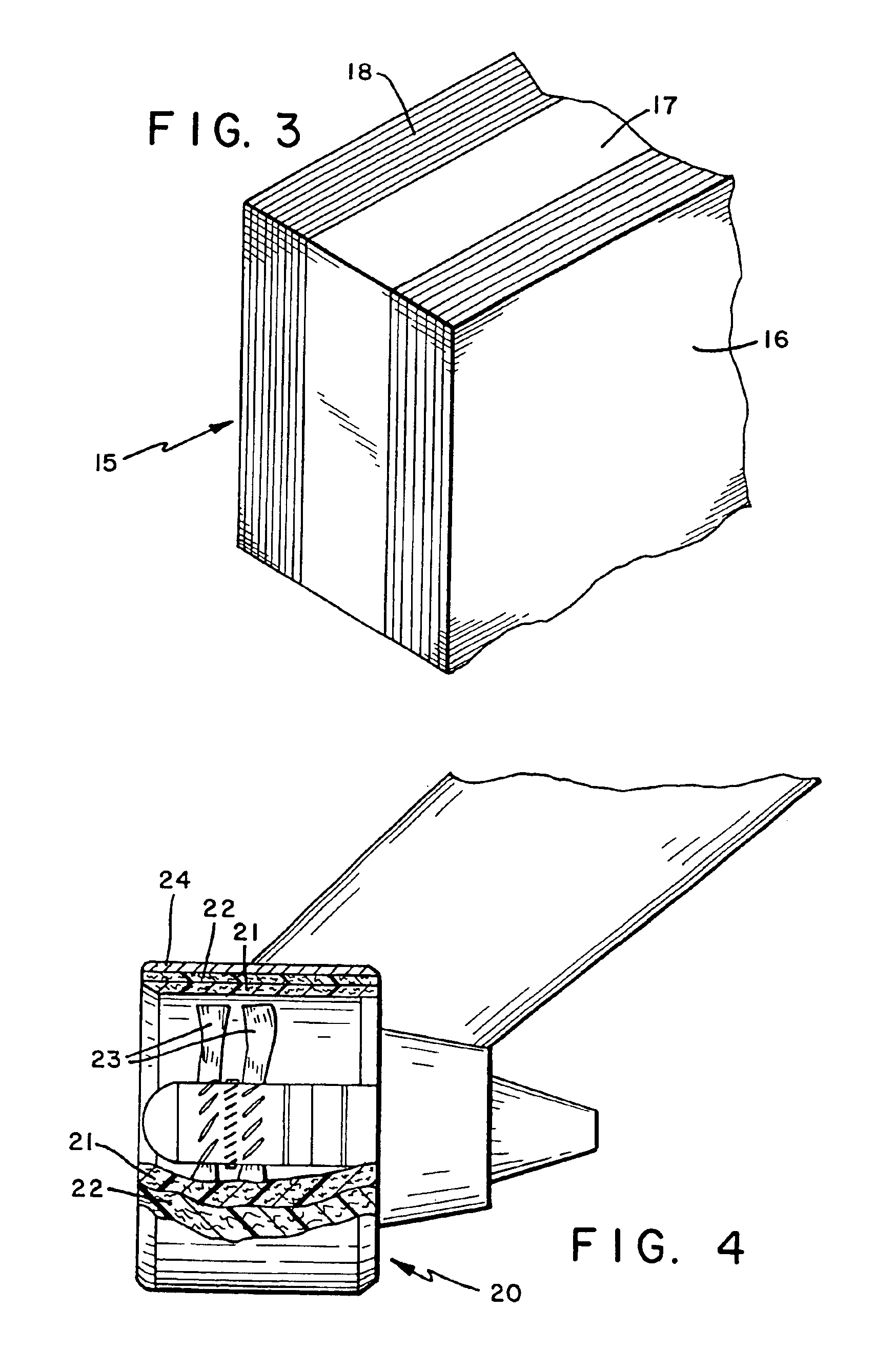
[0017]This armor system is not only effective at containing large, high velocity cutting projectiles but also regular ammunition. Other advantages of this invention are higher performance over the prior art as well as a weight reduction on the order of 30% (for same fiber types).
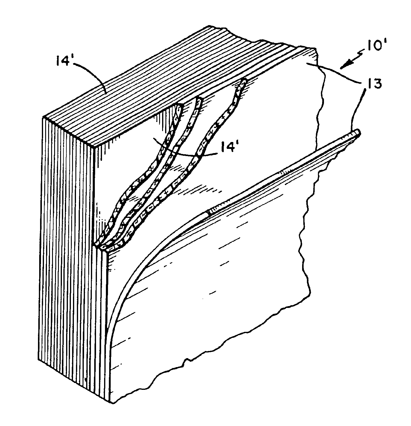
[0020]In the course of developing this armor system, applicants further discovered that when the layers are arranged so that the second layer receives an impact from a projectile first, followed by the first layer, then the system has excellent high velocity impact or ballistic resistance with even less deformation of the non-impact layer. In this system, the first layer (the second layer of the embodiment previously described) is arranged to receive an impact from a projectile prior to the second layer (the first layer of the embodiment previously described). The first layer is resistant to the impact, and the second layer minimizes deformation of the system by the projectile impact to the first layer. Furthermore, any projectile which completely penetrates the first layer is engaged by the second layer to slow its velocity and prevent complete penetration of the second layer. Both layers comprise fibers having a tensile modulus of at least about 200 g / d, an energy to break of at least 8 J / g and a tenacity equal to or greater than about 10 g / d.
[0021]This second armor system is advantageously used against smaller projectiles / fragments, but is ineffective alone against the large, high velocity cutting projectiles which can be contained by the system previously described. These smaller projectiles / fragments may even be from explosions and have velocities similar to or lower than the large projectiles. For vests, blunt trauma can be reduced by this system.

Problems solved by technology

In the summer of 1989, a blade / blade fragment broke away from the turbine engine of an airborne aircraft and severed the aircraft's hydraulic system.
In either event, with the number of woven fabric layers heretofore utilized, these prior art shrouds / shields are not as effective with respect to high velocity cutting impacts of a rapidly rotating engine blade which fractures and is hurled away from the higher power, larger engines of today.
However, this solution suffers the same disadvantage of some of the metallic shields available, excessive weight and expense.
An armor system can stop an impacting object from completely penetrating the system and yet deform (or bulge) so badly on its non-impact side that damage occurs to the equipment or person being protected by the armor system.

Method used


Image

  • Armor systems
  • Armor systems
  • Armor systems

Examples


examples 1-2 (comparative)

[0076]In Example 1, 32 networks of Spectra® 1000 8H satin weave fabric style 985, commercially available from Allied-Signal Corporation, were stitched together in a diamond shape pattern to produce a test sample having an areal density of 176 oz / yd2 (1.22 lb / ft2). In Example 2, a 25 network system was produced just as in Example 1, but having an areal density of 138 oz / yd2 (0.960 lb / ft2).

[0077]Both of these systems were submitted to a 22 caliber 17 grain FSP evaluation test according to MIL-STD-662E. In Example 1, a V50 value of 1797 fps was obtained, while in Example 2, a V50 value of 1611 fps was obtained. Visual observation of the non-impact side of these samples revealed significant deformation (or deflection) of each of the systems.

examples 3 (comparative)

-4

[0078]One layer was comprised of 5 felt networks each having an areal density of about 8 oz / yd2 (0.0556 lbs / ft2) and having a needle punch density of about 500 punches per square inch. The fiber used in these felt networks was Spectra® 1000 2.75 inch (7.0 cm) staple, commercially available from Allied-Signal Corporation. The fiber was carded and cross lapped to a 60 inch (1.52 m) width. The carded webs were stacked up by the cross lapper to produce an 8.0 ounce per square yard fabric, as is known in the art. The fabric was tacked and needled (300 punches per square inch with a #10 needle), and then taken up into a roll. The off line needle punching used a #100 needle and a needle punch density of 200 punches per square inch.

[0079]The other layer was comprised of 20 networks of Spectra® 1000 8H satin weave fabric style 985, commercially available from Allied-Signal Corporation, and having an areal density / weight? of about 5.5 oz / yd2 (0.038 lb / ft2).

[0080]The two layers were stitched...

example 10

[0088]One layer was comprised of 4 felt networks each having an areal density of about 5 oz / yd2 (0.0345 lb / ft2) and having a needle punch density of about 500 punches per square inch, as previously described. The fiber used in these felt networks was Spectra® 1000 2.75 inch (7.0 cm) staple, commercially available from Allied-Signal Corporation.

[0089]The other layer was comprised of 17 networks of Spectra® 900 basket weave (8×8) fabric style 913, commercially available from Allied-Signal Corporation, and each having an areal density of about 15.5 oz / yd2 (0.106 lb / ft2). The total areal density for the system was 1.97 lb / ft2.

[0090]These two layers were formed into a system for testing, and the felt layer was facing the incoming projectile. At level 2, this system performed better than Example 9 above, and without significant deformation.


PUM

PropertyMeasurementUnit
lengthaaaaaaaaaa
lengthaaaaaaaaaa
ballistic limit velocityaaaaaaaaaa

Abstract

An armor system useful, for example, as a shroud, comprising a first pliable, cut resistant fibrous layer and a second pliable fibrous layer is disclosed. The first layer is arranged to receive an impact from a large projectile prior to the second layer and engages the projectile to slow its velocity. The second layer is substantially coextensive with the first and dissipates the incoming energy of the impact to resist complete penetration of the second layer by the projectile, preferably by deforming in response to the impact. Both layers comprise fibers having a tensile modulus of at least about 200 g / d, and an energy-to-break of at least about 8 J / g and a tenacity equal to or greater than about 10 g / d. In another embodiment, the layers are reversed relative to the impact face of the system so that the second layer becomes the first layer and is resistant to projectiles impacting the system, while the first layer becomes the second layer and resists deformation of the system by projectile impacts. Any projectile which completely penetrates the first layer is engaged by the second layer to slow its velocity and prevent complete penetration of the second layer. This armor system provides excellent ballistic resistance with enhanced deformation control.

Description

[0001]This application is a divisional of U.S. Ser. No. 09 / 325,212, filed on Jun. 3, 1999, now U.S. Pat. No. 6,276,254; which is a continuation of U.S. Ser. No. 08 / 440,162, filed on May 12, 1995, now U.S. Pat. No. 6,003,424; which is a continuation of U.S. Ser. No. 08 / 112,925, filed on Aug. 30, 1993, now U.S. Pat. No. 5,440,965; which is a continuation of U.S. Ser. No. 07 / 924,566, filed on Aug. 5, 1992, now U.S. Pat. No. 5,343,796; which is a continuation of U.S. Ser. No. 07 / 490,179, filed Mar. 8, 1990, now abandoned. The entire disclosure of the prior application(s) is hereby incorporated by reference in its entirety.BACKGROUND OF THE INVENTION[0002]1. Field of the Invention[0003]The present invention relates to armor systems. More particularly, the present invention relates to a first multi-layer armor system which can be a shroud for the containment of large, high velocity cutting projectiles, and to a second multi-layer armor system which is high velocity impact / ballistic resist...

Claims


Application Information

Patent Timeline
Patent Type & Authority Patents(United States)
IPC IPC(8): B32B5/26B32B5/22D04H13/00F41H5/04F41H5/00
CPCB32B5/26D04H13/002F41H5/0485D04C1/02D03D1/0041D03D1/0052D03D11/02Y10S428/911D10B2321/0211
Inventor CORDOVA, DAVID SOLARESKIRKLAND, KEVIN MARK
Owner HONEYWELL INT INC
Why Eureka
Try Eureka