Indwelling needle assembly

a technology of indwelling needles and needles, which is applied in the direction of infusion needles, trocars, catheters, etc., can solve problems such as loading in operation, and achieve the effect of high safety

Inactive Publication Date: 2011-03-10
TERUMO KK
View PDF9 Cites 29 Cited by
  • Summary
  • Abstract
  • Description
  • Claims
  • Application Information

AI Technical Summary

Benefits of technology

[0044]This ensures that at the time of discarding the inner needle or the like or in other similar situations, the accident that the w

Problems solved by technology

In short, in the conventional indwelling needle assembly as above-mentioned, there is a problem that when the inner needle hub is moved in the proximal direction so as to pull the inner needle hub out of the outer needle and to release the p

Method used


Image

  • Indwelling needle assembly
  • Indwelling needle assembly
  • Indwelling needle assembly

Examples


first embodiment

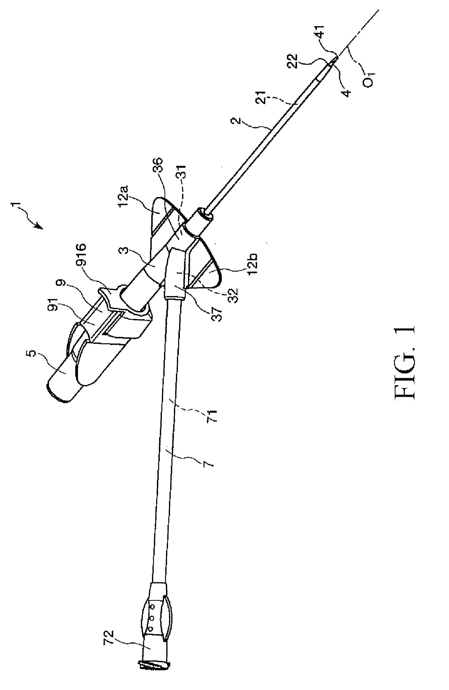
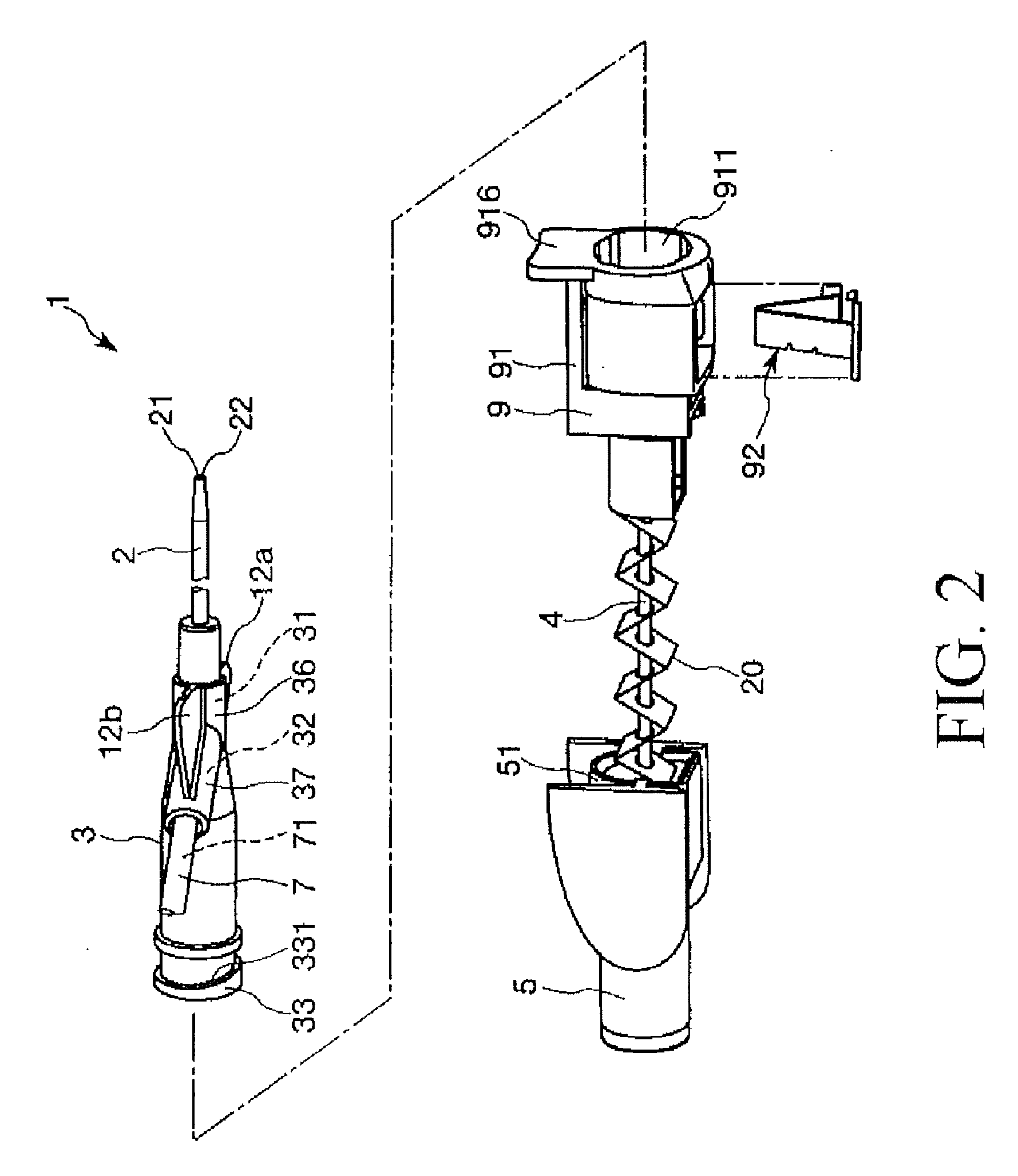
[0061]FIG. 1 is a perspective view showing a first embodiment of the indwelling needle assembly according to the present invention; FIG. 2 is an exploded perspective view of the indwelling needle assembly shown in FIG. 1; FIG. 3 is a sectional view showing an outer needle hub, an inner needle, an inner needle hub, a protector, etc. of the indwelling needle assembly shown in FIG. 1; FIG. 4 is a sectional view taken along line A-A of FIG. 3; FIG. 5 is a sectional view showing the outer needle hub, the inner needle, the inner needle hub, the protector, etc. of the indwelling needle assembly shown in FIG. 1; FIG. 6 is a perspective view showing a connection member of the protector of the indwelling needle assembly shown in FIG. 1; and FIGS. 7 and 8 are each bottom views showing schematically the outer needle hub and the connection member of the protector in the indwelling needle assembly shown in FIG. 1.

[0062]Incidentally, in the following, the left side in FIGS. 2, 3 and 5 will be refe...

second embodiment

[0154]FIG. 9 is a bottom view showing schematically an outer needle hub and a connection member of a protector in a second embodiment of the indwelling needle assembly according to the present invention.

[0155]Incidentally, in the following description, the right side in FIG. 9 will be referred to as a “proximal” side and the left side as a “distal” side. Further, in FIG. 9, of the connection member of the protector, only a first part and a projecting piece are drawn.

[0156]The second embodiment will be described below, referring mainly to differences from the above-described first embodiment, and descriptions of the same items as mentioned above will be omitted.

[0157]As shown in FIG. 9, in the indwelling needle assembly 1 according to the second embodiment, an opposed surface 926 of the projecting piece 924 of a connection member 92 which is opposed to a sliding surface 331 of a rib 33 is tilted relative to the center axis O1 of an inner needle 4.

[0158]Further, the tilt angle of the ...

third embodiment

[0162]FIG. 10 is an exploded perspective view showing a third embodiment of the indwelling needle assembly according to the present invention; FIGS. 11 and 12 are each sectional views showing an outer needle hub, an inner needle, a protector, etc. of the indwelling needle assembly shown in FIG. 10; FIG. 13 is a perspective view showing a connection member of the protector in the indwelling needle assembly shown in FIG. 10; and FIG. 14 is a perspective view showing a shutter member of the protector in the indwelling needle assembly shown in FIG. 10.

[0163]Incidentally, in the following description, the left side in FIGS. 10, 11 and 12 will be referred to as a “proximal” side and the right side as a “distal” side.

[0164]The third embodiment will be described below, referring mainly to differences from the above-described first embodiment, and descriptions of the same items as above will be omitted.

[0165]As shown in FIGS. 10 to 14, in the indwelling needle assembly 1 according to the thi...


PUM


Abstract

An indwelling needle assembly comprises an inner needle secured to an inner needle hub, a hollow outer needle in which the inner needle is positioned, an outer needle hub secured to the outer needle and having a projection at the proximal end, and an elastic protector which has a connection member with a projecting part engageable with the projection and which is detachably connected to the outer needle hub by the engagement of the projecting part with the projection. The projection of the outer needle hub comprises a tilted sliding surface on which the projecting part slidingly moves. The connection member can take a first state in which the projecting part engages the projection and a second state in which the projecting part is disengaged from the projection. When changing from the first state to the second state, the projecting part slidingly moves along the sliding surface of the projection.

Description

TECHNICAL FIELD[0001]The present invention relates to an indwelling needle assembly to puncture and indwell in a blood vessel at the time of infusion, for example.BACKGROUND ART[0002]At the time of carrying out an infusion on a patient or in other similar situations, an indwelling needle connected with an infusion line is made to puncture a blood vessel of the patient and is kept indwelling there during infusion.[0003]Such an indwelling needle (indwelling needle assembly) is composed of a hollow outer needle, an outer needle hub secured to the proximal end (base end) of the outer needle, an inner needle which is inserted into the outer needle and which has a sharp needle tip at its distal end, an inner needle hub secured to the proximal end (base end) of the inner needle, and a protector detachably connected to the outer needle hub. The outer needle hub is provided with a main pipe having a flow path communicating with a lumen of the outer needle and a side pipe having a branch flow...

Claims


Application Information

Patent Timeline
IPC IPC(8): A61B17/34
CPCA61M5/158A61M5/3275A61M2005/325A61M25/0637A61M25/0631
Inventor TANABE, HIDENORIHASHIMOTO, KAZUHIROMURASHITA, TAKATO
Owner TERUMO KK
Why Eureka
Try Eureka