
Magnetically Stowable drinking cup

Inactive Publication Date: 2011-03-17
VASIC STEVAN P
View PDF20 Cites 12 Cited by
  • Summary
  • Abstract
  • Description
  • Claims
  • Application Information

AI Technical Summary

Benefits of technology

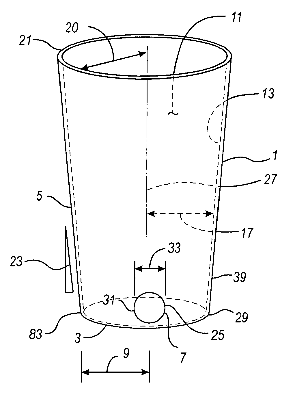
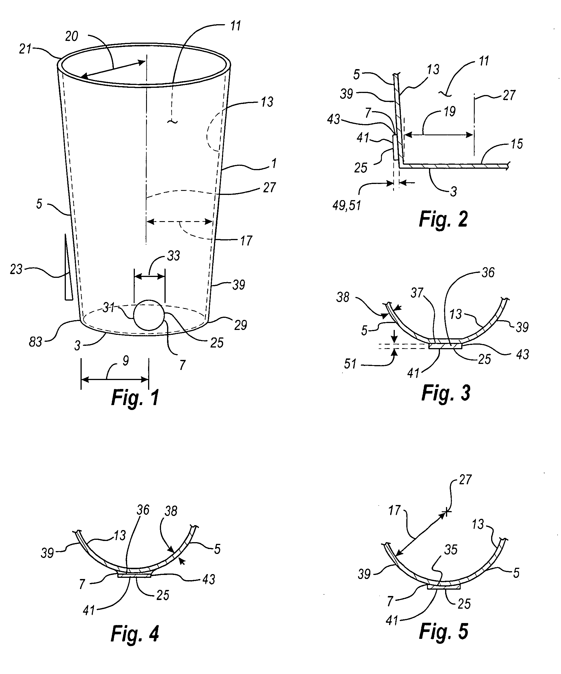
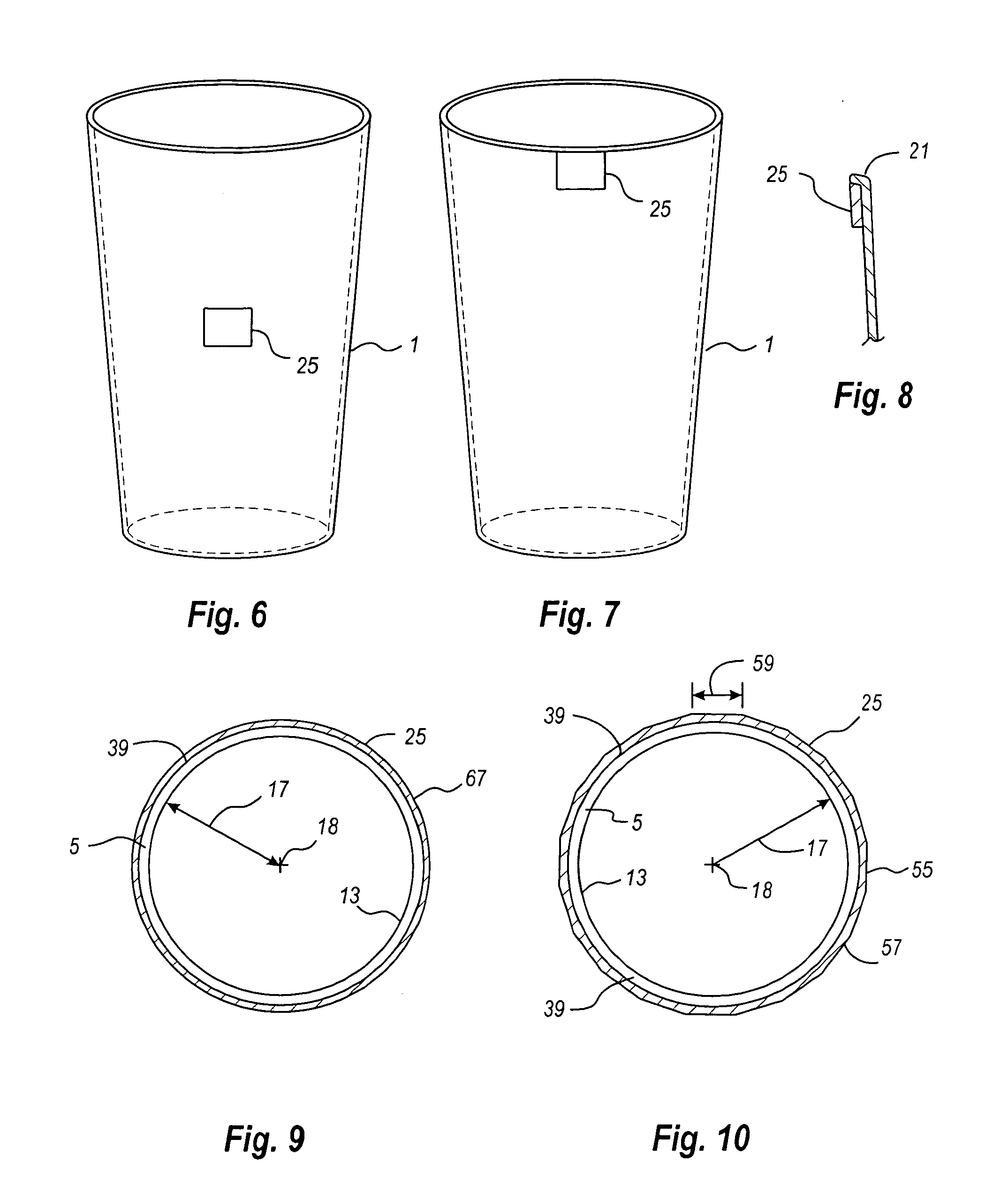
[0005]The magnetically stowable and stackable drinking cup of the present invention has a bottom, a side wall, and a magnetic element, the magnetic element being affixed to magnetic element seat on the outside surface of the side wall or the outside surface of the bottom, or being imbedded in the side wall or the bottom. The bottom has a bottom periphery which is affixed to and sealed to the side wall base of the side wall, thereby forming the liquid chamber of the cup. The liquid chamber of the cup is tapered, the liquid chamber radius and the side wall radius from the center axis increasing from the bottom to the lip of the cup. The liquid chamber and side wall tapering, which is a common feature of drinking cups to provide for stacking will also provide for the stacking of the cup of the present invention. The extent to which a cup of the present invention may be inserted in another cup of the present invention for stacking purposes will depend on the position and the size of the magnetic element and magnetic element seat. The magnetic element may be positioned on the side wall or the bottom of the cup. The magnetic element may be imbedded in the side wall or the bottom of the cup for appearance, durability and ease of cleaning purposes.
[0006]Positioning of the magnetic element near the side wall base together with the side wall tapering, facilitates the stacking of the cups when the cups are not in use. Positioning the magnetic element near the side wall base also facilitates stowing of the cups on a vertical ferro-magnetic surface, such as a refrigerator door, in an inverted configuration and reduces interference with the ordinary use of the cup for drinking purposes. If the magnetic element is of sufficient size and strength, the stowage orientation of the cup may be selected by the user without regard to the position of the magnetic element.
[0008]The cup of the present invention may have a circular bottom, a circular side wall and a circular liquid chamber. However, other embodiments utilizing other shapes, such as a square with rounded corners, may be utilized. Regardless of the shape, stacking may be facilitated by side wall tapering.

Problems solved by technology

Caretakers of children and particularly caretakers of small children face a daily challenge of many demands being placed on their time to meet the needs of the children.

Method used


Image

  • Magnetically Stowable drinking cup
  • Magnetically Stowable drinking cup
  • Magnetically Stowable drinking cup

Examples


Embodiment Construction

[0035]Referring first to FIG. 1, a preferred embodiment of the magnetically stowable and stackable drinking cup 1, hereinafter referred to as the “cup”, is shown. This embodiment of the cup 1 has a bottom 3, a side wall 5, a magnetic element seat 7, and a magnetic element 25 affixed to the magnetic element seat. The bottom 3 has a bottom periphery 83 which is affixed to and sealed to the side wall base 29 of the side wall 5, thereby forming the liquid chamber 11 of the cup. For the embodiment shown in FIG. 1, the bottom 3 is circular or approximately circular having a bottom radius 9. For this specification and including the claims, the use of the term “circular” shall be defined to mean circular or approximately circular. Referring also to FIG. 2, the liquid chamber 11 of the cup which is confined by the side wall inside surface 13 and the bottom inside surface 15 is tapered 23, the liquid chamber radius and the side wall radius 17 from the center axis 27 increasing at a uniform or...


PUM


Abstract

A magnetically stowable and stackable drinking cup having a bottom, a side wall, and a magnetic element, the magnetic element being affixed to a magnetic element seat on the side wall or the bottom or imbedded in the side wall or the bottom. The liquid chamber and side wall tapering provide for stacking.

Description

BACKGROUND OF THE INVENTION[0001]Caretakers of children and particularly caretakers of small children face a daily challenge of many demands being placed on their time to meet the needs of the children. One of those demands is the steadily growing collection of soiled dishes. Another demand is assisting small children in obtaining basic necessities such as getting a drink of water or other beverage.[0002]One objective of the present invention is to provide a drinking cup that can be readily stowed after use, reaccessed and reused by an individual to whom the cup is assigned.[0003]Another objective of the present invention is to provide a drinking cup with a magnetic element which provides for stowing of the cup for re-use on a refrigerator or other ferro-magnetic surface.[0004]A further objective of the present invention is to provide a magnetically stowable drinking cup which is stackable for storage during periods of non-use.SUMMARY OF THE INVENTION[0005]The magnetically stowable ...

Claims


Application Information

Patent Timeline
IPC IPC(8): B65D25/24B65D21/02
CPCA47G2200/106A47G19/2205
Inventor VASIC, STEVAN P.
Owner VASIC STEVAN P
Learn More