Pin cutting tool

a cutting tool and pin technology, applied in manufacturing tools, osteosynthesis devices, transportation and packaging, etc., can solve the problems of unfavorable use, unfavorable use, and unfavorable pin rotation

Active Publication Date: 2011-03-17
STRYKER EURO OPERATIONS HLDG LLC
View PDF9 Cites 4 Cited by
  • Summary
  • Abstract
  • Description
  • Claims
  • Application Information

AI Technical Summary

Benefits of technology

[0012]It is a further aspect of the invention to provide an easy pin cu

Problems solved by technology

However, by actuating both levers, unwanted forces can sometimes be transferred to the pin.
Furthermore, the use of two large ha

Method used


Image

  • Pin cutting tool
  • Pin cutting tool
  • Pin cutting tool

Examples


first embodiment

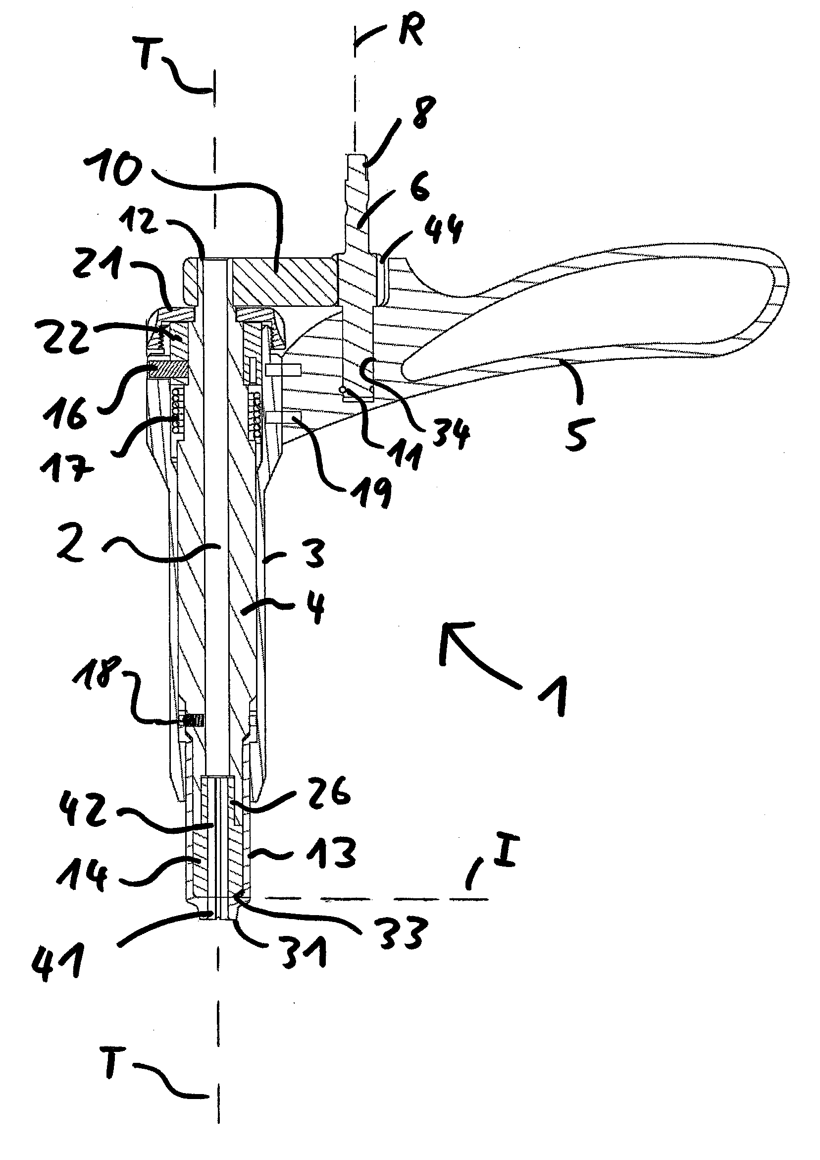
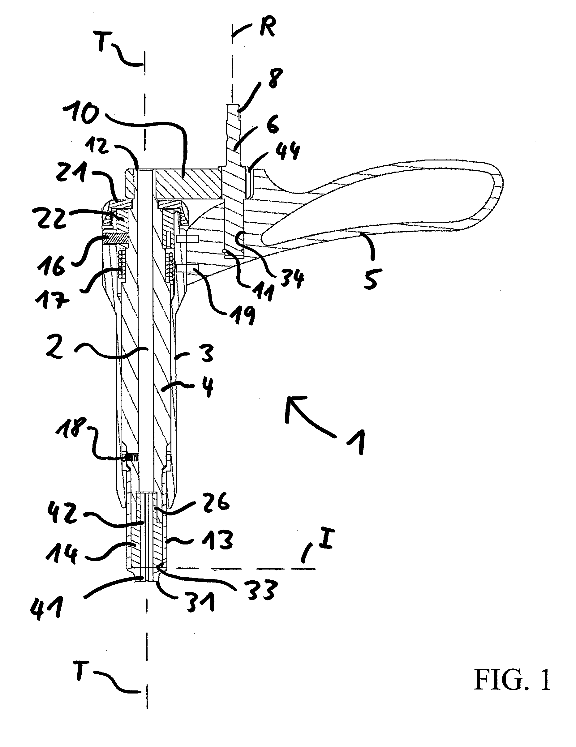
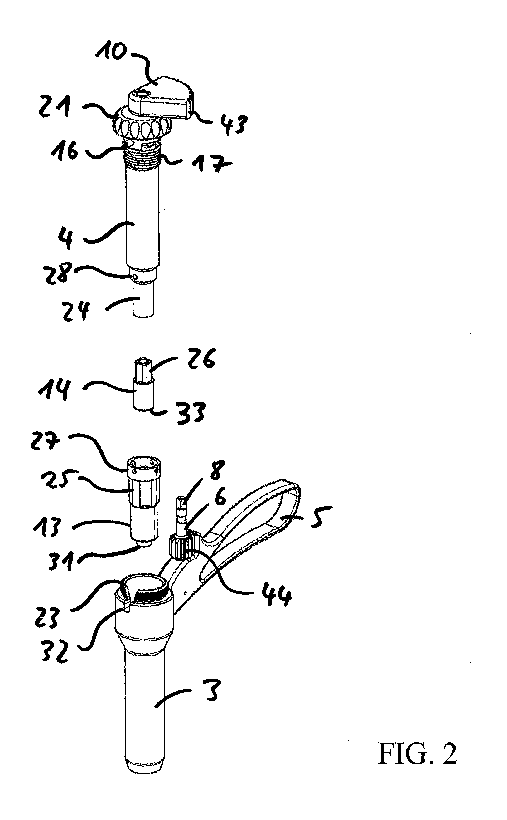
[0027]Referring to FIGS. 1 and 2, there is shown a cross-section of a pin cutting tool or pin cutter 1, i.e. a tool for breaking a shaft of a pin with or without a screw, according to the invention, which embodiment omits the turning handle or crank 7 (see FIG. 4) of the cutter 1. FIG. 1 is explained in connection with FIG. 2 showing an exploded perspective view of the cutter. A pin or screw (not shown) to be shortened is to be introduced into the through bore 2, defining the longitudinal axis T of the cutter 1. The through bore 2 being defined through introduction of several components as explained below has a remaining inner cavity and dimension to accommodate a pin. The pin, which is to be broken, is usually already introduced in bone material and fixed. The longitudinal axis of the pin is also the axis T and the cutter 1 has to be positioned accordingly on such a pin.

[0028]The cutter 1 comprises a stationary portion and a rotating portion.

[0029]The stationary portion comprises a...

second embodiment

[0042]FIG. 5 shows a simplified perspective view from above of a pin cutter 1 according to the invention in a slightly rotated position; and FIG. 6 shows a view from below on the pin cutter 1 according to FIG. 5, when the handle 7 is slightly rotated.

[0043]Pin cutter 1 comprises as stationary portion of the cutter 1 an outer first tubular element 3 directly attached to handle 5. Opposite to the handle 5, the tubular element 3 comprises a mounting plate 15, within which several bearings are provided for fixing a geared transmission. Turning handle 7 is mounted or unitary with gear axle 6 mounted on plate 15. Teeth of gear 6 mesh with a transmission gear 20 for a gear reduction. Transmission gear 20 mesh with teeth 43 of cogwheel 10. Cogwheel 10 is fixedly connected with the second inner tubular element 4. The upper portions of the side walls 29 of the outer tubular element 3 provide abutments for the cogwheel 10.

[0044]Turning handle 7 rotates cogwheel 10 and thus the second inner tub...

third embodiment

[0050]Finally FIG. 7 shows an exploded perspective view of a pin cutter according to the invention having a different zero position mechanism. Second tubular element 4 comprises an outer square profile engaging a complementary profile in rotating element 62. Rotating element is a sleeve comprising at its circumference four angularly separated tangentially inclined surfaces 64, i.e. covering 90 degrees with a longitudinal oriented connection slope 66. A blocking element 61 is positioned distal to the rotating element and comprises complementary inclined surfaces 63. Blocking element 61 has an outer square profile engaging a complementary profile within the outer tubular element 3. On the opposite side of the blocking element 61 spring 17 is located abutting against nut 65, which is fixed inside the device 1 by being screwed on the inner tubular element 4. Nut 65 is located at a specific position along the longitudinal axis T. Turning the inner tubular element 4 rotates element 62, wh...


PUM

PropertyMeasurementUnit
Angleaaaaaaaaaa
Angleaaaaaaaaaa

Abstract

A tool for breaking a shaft has a first and a second tubular element, both provided with inner through bores adapted to receive a first and second portion of a shaft in a first position of the tool. A first handle is fixedly connected with the first tubular element and the second tubular element is connected to a second handle. A bottom surface of the second tubular element is in contact with a neck surface of the first tubular element forming a shearing plane perpendicular to the main axis of the tool. A rotation between the two tubular elements around this axis creates a twisting movement of the two shaft portions received within the two tubular elements, and shears the shaft portions at the shearing plane. The second handle turns the first tubular element around an axis and has a gear engaging the second tubular element for transmitting the rotation of the second handle into a rotation of the second tubular element for producing the twisting movement.

Description

BACKGROUND OF THE INVENTION[0001]The present invention relates to a tool for breaking a shaft of a surgical pin or screw, e.g. a Schanz-type screw, in order to reduce the excess portion of the pin extending beyond a fixator in bone surgery.[0002]External fixators are widely used in bone surgery in order to reduce the fracture of a bone and to maintain the bone fragments in a fixed relationship. Commonly, pins are inserted into the bone for connection to the fixator. Such pins and / or screws often are of an undefined or uniform length, making it desirable for their excess shaft portions projecting beyond an exposed surface to be removed. For this purpose, various pin cutter devices have been developed.[0003]For instance, U.S. Pat. No. 6,085,425 relates to a surgical cutter having two cooperating jaws pivotally secured in between two holding plates by floating bolts, and having said jaws pivotally secured to two very long handles in order to build up the large leverage force necessary....

Claims


Application Information

Patent Timeline
IPC IPC(8): B26F3/00
CPCB23D29/02A61B17/8863Y10T225/371Y10T225/364
Inventor AEBI, THISDOMINIK, ROBERT
Owner STRYKER EURO OPERATIONS HLDG LLC
Why Eureka
Try Eureka