This helps you quickly interpret patents by identifying the three key elements:
Problems solved by technology
Method used
Benefits of technology
Benefits of technology
[0004]In an inventive linear motor, comprising a stator and at least one rotor, the stator has at least two stator modules. Each stator module has a coil arrangement and, seen in a longitudinal extension of the respective stator module, at least at one end of the coil arrangement, a displacement sensor. This means, the displacement sensors are configured separately from the respective coil arrangements. This brings about advantages in manufacturing, as the coil arrangement and the displacement sensors can be manufactured and tested independently from each other. In addition, a magnetic shielding of the displacement sensors is easier to accomplish, because it does not need to be provided within the coil arrangement. The displacement sensors and the coil arrangement can be fitted into a housing, which itself provides said shielding, namely from magnetic influences of the coil arrangement and, if applicable, from possible influences of a coil arrangement of another stator module. Each stator module is disposed along a travel path of the respective rotor in an area of the respective stator module. Each displacement sensor has a detection range, within which the displacement sensor can detect the rotor, as long as the rotor has at least one portion located in the detection range. Each coil arrangement has an interaction range, within which, in case of energizing, the coil arrangement comes into interaction with the rotor and urges the latter in a driving direction, as long as the rotor ihas at least one portion located in the interaction range. The at least two stator modules and the at least one rotor are disposed such that, at all times, a portion of the at least one rotor is located in the detection range of at least one displacement sensor and another portion of this rotor in the interaction range of at least one coil arrangement of the at least two stator modules. It is thereby guaranteed that a position of the at least one rotor can be determined any time and that the rotor can be moved any time in a driving direction by means of the stator.
[0009]It is furthermore preferred that the control circuit is adapted to switch-off at least one coil arrangement of one of the at least two stator modules, if the control circuit determines that the determined position of the respective rotor corresponds to falling below a predetermined first penetration measure of this rotor into a predetermined section of the interaction range of the one coil arrangement. It is thus checked in which area of the interaction range of the respective coil arrangement the rotor penetrated. This is required in order to be able to prevent the respective coil arrangement for example from being switched off, if the rotor, coming from a terminal position, is supposed to enter the interaction range of this respective coil arrangement and to pass through the interaction range. Switching-off coil arrangements has the advantage of wasting as little energy as possible.
[0011]In addition or as an alternative, the control circuit may be furthermore adapted to switch-on additionally, i.e. to energize, at least one coil arrangement of one of the at least two stator modules, if the control circuit determines that the determined position of the respective rotor corresponds to a predetermined second penetration measure of the at least one rotor into the interaction range of the one coil arrangement or to exceeding this second penetration measure. This is in particular practical, if the at least one rotor, coming from another stator module, penetrates the interaction range of the one coil arrangement and an immediate additional switching-on of the other coil arrangement is not desired. This measure serves the purpose that the stator does not function unnecessarily while idling and thus wasting energy.
Problems solved by technology
This is disadvantageous in that the Hall sensors need to be shielded against magnetic influences.
The challenge is now to assure that the displacement sensors are able to continue to detect a rotor of a linear motor.
Thereby, the structure of such a stator becomes very expensive.
Method used
Image
Click on the blue label to locate the original text in one second.
Reading with bidirectional positioning of images and text.
Examples
first embodiment
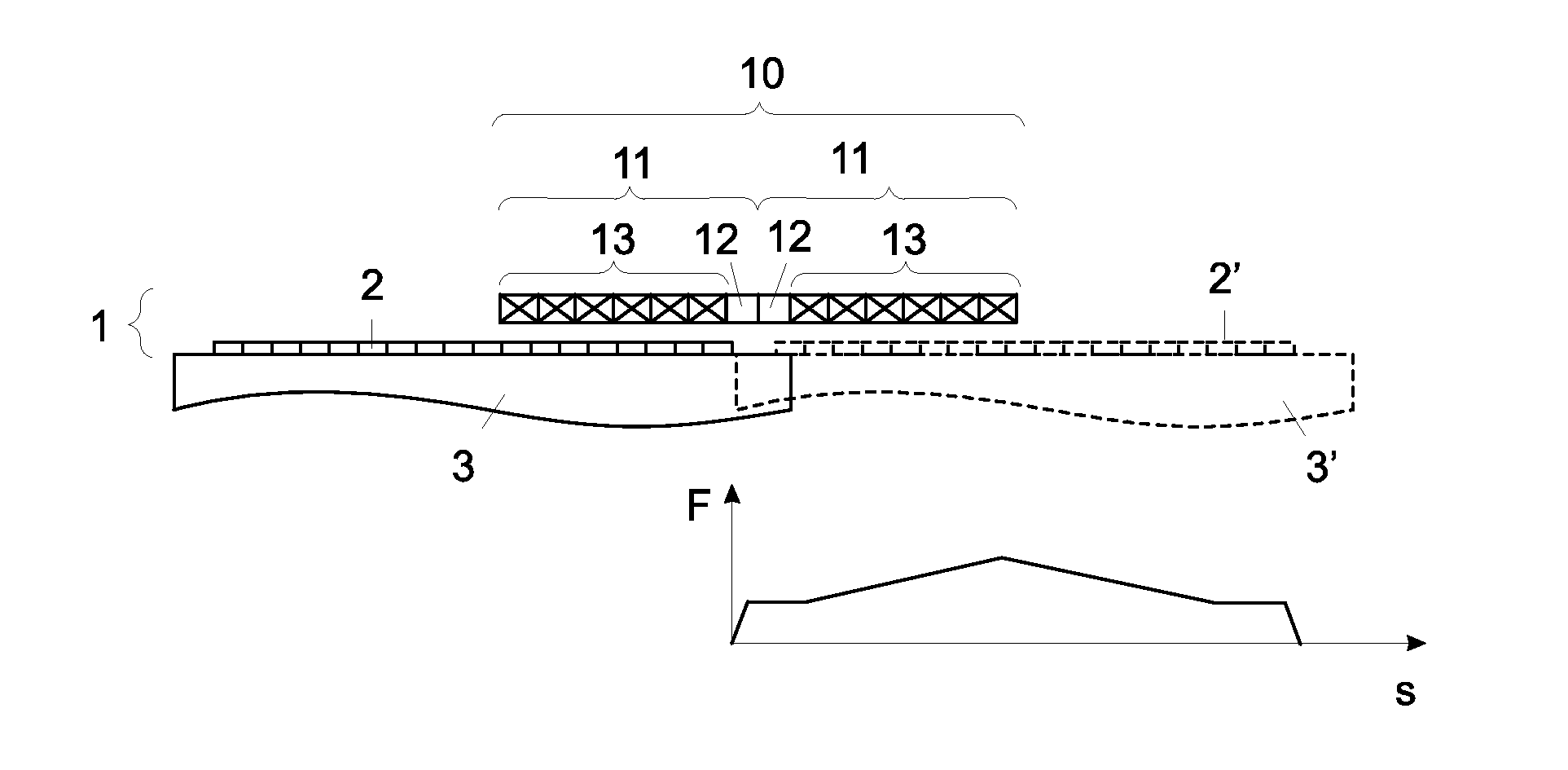
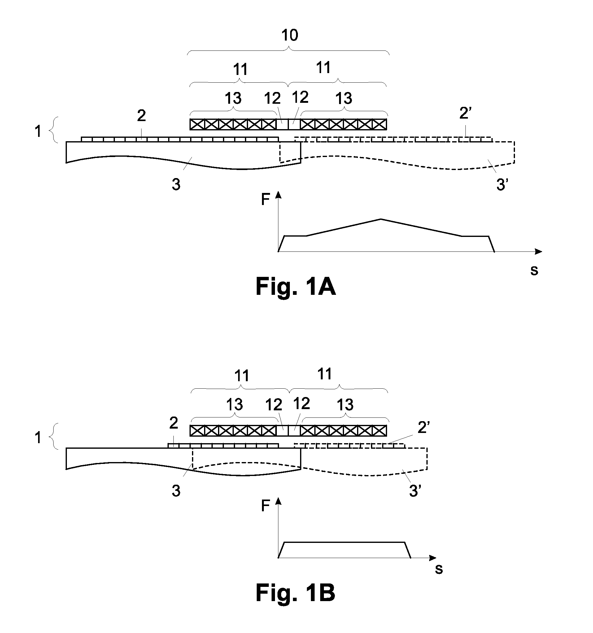
[0030]According to the invention shown in FIG. 1A, stator modules 11, 11 preferably each have a coil arrangement 13 and a displacement sensor 12 and, for illustration purposes, the stator modules 11, 11 have the same structure. The displacement sensors 12, 12 are configured at ends of the stator modules 11, 11 facing each other. The stator modules 11, 11 extend respectively along an area of an exemplary linear travel path of the panel to be moved 3 in the area of the respective stator module 11. In the arrangement shown, the stator modules 11, 11 abut against each other, i.e. they have a very small distance to each other or they do not have any distance at all. Preferably, a shape of a respective stator module 11, seen in longitudinal extension, follows a course of the travel path of the panel to be moved 3 in the area of the respective stator module 11.
[0031]A diagram, illustrated on the bottom of FIG. 1A, diagrammatically shows a characteristic of a driving force F of the linear m...
second embodiment
[0044]An arrangement shown in FIG. 2A according to the invention differs from the arrangement shown in FIG. 1A in that the displacement sensors 12, 12 are configured at ends of the stator modules 11, 11 facing away from each other. As the stator modules 11, 11, practically do not have any distance to each other, the stator modules 11, 11 virtually form a single stator module 11, which, at both ends, has respectively one displacement sensor 12 with a coil arrangement 13 disposed therebetween.
[0045]When the rotor 2 begins to move, it gradually enters more and more interaction ranges of coils of initially the left and then also the right coil arrangement 13, 13, which results in an increase of the driving force F of the linear motor 1 and thus of the speed of the rotor 2. Thereupon, as long as the rotor 2 is located in the interaction range of all coils of both the left and the right coil arrangement 13, 13, the driving force F of the linear motor 1 remains almost constant. From a pred...
third embodiment
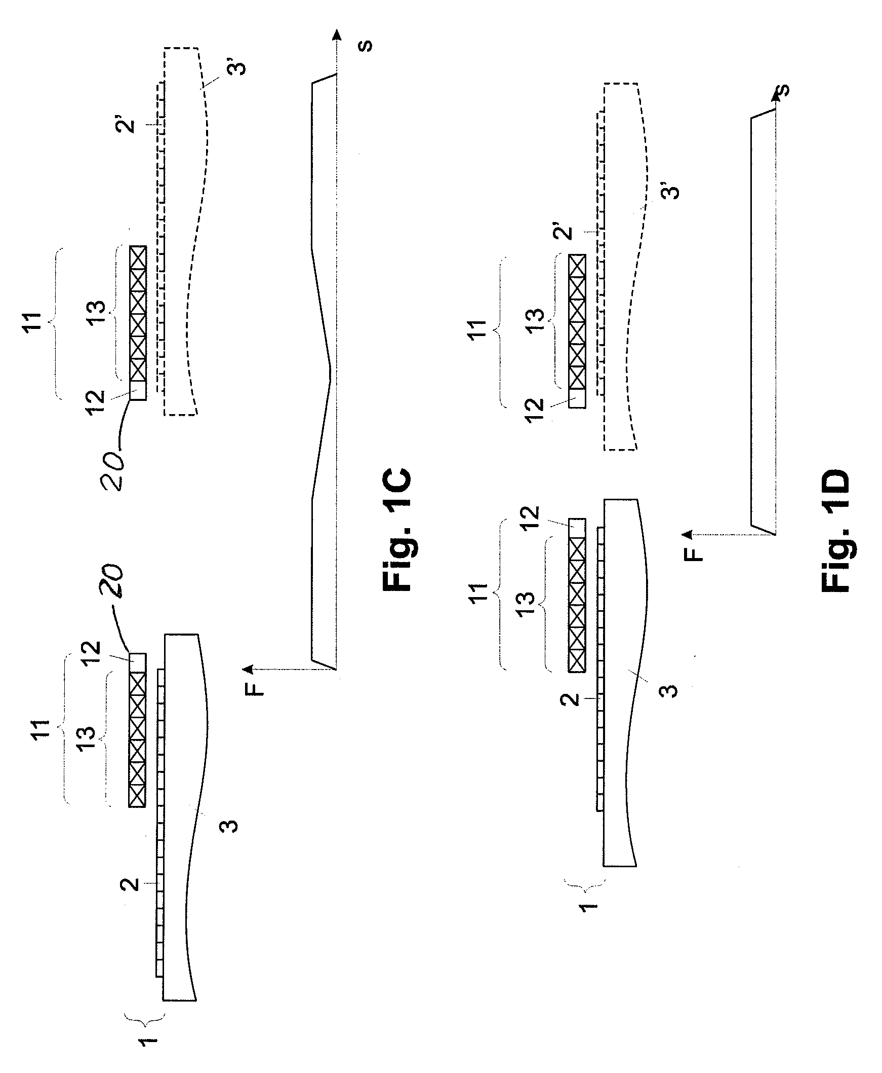
[0049]An arrangement according to the invention shown in FIG. 3A differs from the arrangement shown in FIG. 1A in that the right stator module 11 is disposed rotated about 180° such that the left stator module 11, with its displacement sensor side end, is disposed to face a coil side end of the right coil arrangement 13.
[0050]When the rotor 2 starts to move, all coils of the left coil arrangement 13 are in interaction with the rotor 2, which results in the increase in driving force F of the linear motor 1 illustrated in the diagram in FIG. 3A. As long as the rotor 2 is not yet located in the interaction range of the right coil arrangement 13, the driving force F remains essentially constant. When the rotor 2 enters the interaction range of the right coil arrangement 13, the driving force F increases gradually up to a maximum, as long as the rotor 2 is still located in the interaction ranges of all coils of the left coil arrangement 13. In the meantime, the rotor 2 gradually enters t...
PUM
Abstract
A linear motor is disclosed, which has a stator and at least one rotor, the stator having at least two stator modules. Each stator module has a coil arrangement and, seen in longitudinal extension of the respective stator module, at least at one end, a displacement sensor. Each stator module is disposed along a travel path of the respective rotor in an area of the respective stator module. Each displacement sensor has a detection range, within which it can detect a rotor, as long as the latter is located at least partially in the detection range. Each coil arrangement has an interaction range, within which, in case of energizing, the coil arrangement comes into interaction with the rotor and urges the latter in a driving direction, as long as the rotor is located with at least one portion in the interaction range. The at least two stator modules and the at least one rotor are disposed such that, at all times, a portion of the at least one rotor is located at least in the detection range of a displacement sensor and another portion of this rotor at least in the interaction range of a coil arrangement of the at least two stator modules.
Description
FIELD OF THE INVENTION[0001]The invention relates to an arrangement of stator modules in a linear motor.BACKGROUND OF THE INVENTION[0002]Linear motors are very well known. In order to be able to determine a position of a rotor, the linear motor stators usually have displacement sensors in the shape of Hall sensors. Usually, the Hall sensors are incorporated into the linear motor stator such that they are disposed between coils of such a stator. This is disadvantageous in that the Hall sensors need to be shielded against magnetic influences. These magnetic influences are generated on account of current-carrying coil windings in the stator and on account of a possibly existing magnetic keeper of the stator. The challenge is now to assure that the displacement sensors are able to continue to detect a rotor of a linear motor. Thereby, the structure of such a stator becomes very expensive.SUMMARY OF THE INVENTION[0003]One object of the invention is to reduce or to eliminate the above dis...
Claims
Application Information
Patent Timeline
Application Date:The date an application was filed.
Publication Date:The date a patent or application was officially published.
First Publication Date:The earliest publication date of a patent with the same application number.
Issue Date:Publication date of the patent grant document.
PCT Entry Date:The Entry date of PCT National Phase.
Estimated Expiry Date:The statutory expiry date of a patent right according to the Patent Law, and it is the longest term of protection that the patent right can achieve without the termination of the patent right due to other reasons(Term extension factor has been taken into account ).
Invalid Date:Actual expiry date is based on effective date or publication date of legal transaction data of invalid patent.

