Zoom lens system, imaging device and camera
- Summary
- Abstract
- Description
- Claims
- Application Information
AI Technical Summary
Benefits of technology
Problems solved by technology
Method used
Image

Examples
embodiments 1 to 11
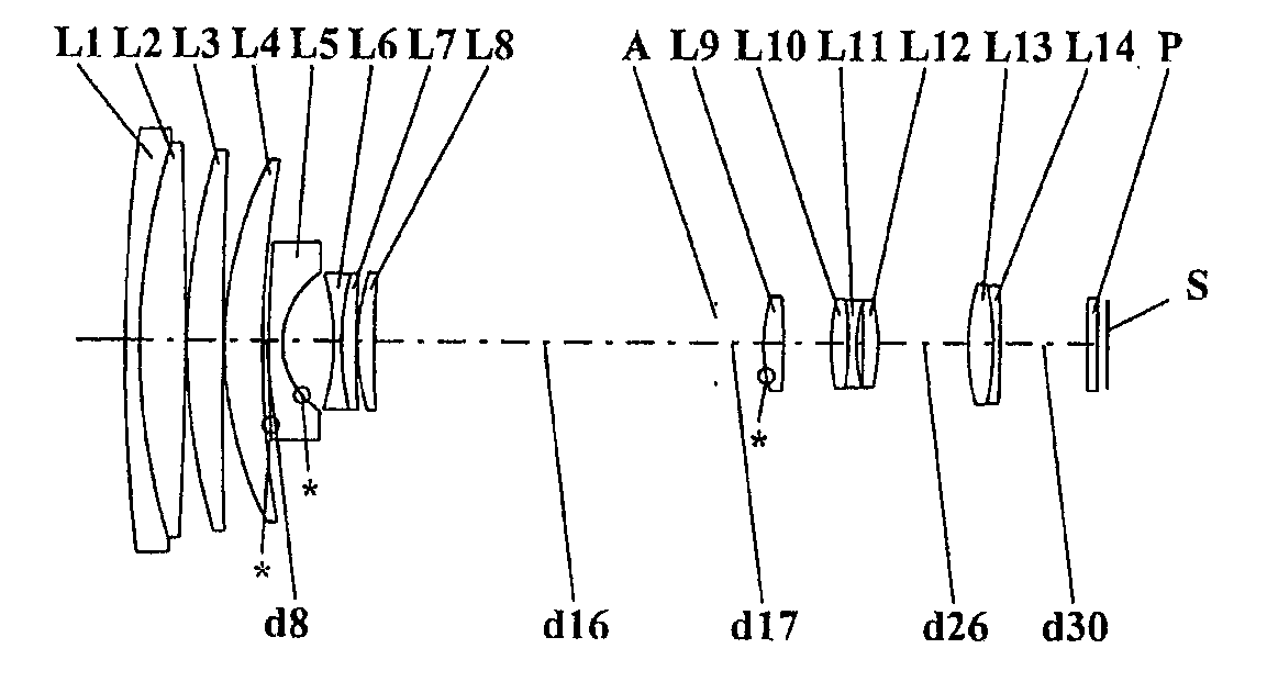
[0091]FIGS. 1, 4, 7, 10, 13, 16, 19, 22, 25, 28, and 31 are lens arrangement diagrams of zoom lens systems according to Embodiments 1 to 11, respectively.
[0092]Each of FIGS. 1, 4, 7, 10, 13, 16, 19, 22, 25, 28, and 31 shows a zoom lens system in an infinity in-focus condition. In each Fig., part (a) shows a lens configuration at a wide-angle limit (in the minimum focal length condition: focal length fW), part (b) shows a lens configuration at a middle position (in an intermediate focal length condition: focal length fM=√(fW*fT)), and part (c) shows a lens configuration at a telephoto limit (in the maximum focal length condition: focal length fT). Further, in each Fig., an arrow of straight or curved line provided between part (a) and part (b) indicates the movement of each lens unit from a wide-angle limit through a middle position to a telephoto limit. Moreover, in each Fig., an arrow imparted to a lens unit indicates focusing from an infinity in-focus condition to a close-object i...
embodiment 12
[0264]FIG. 34 is a schematic construction diagram of a digital still camera according to Embodiment 12. In FIG. 34, the digital still camera comprises: an imaging device having a zoom lens system 1 and an image sensor 2 composed of a CCD; a liquid crystal display monitor 3; and a body 4. The employed zoom lens system 1 is a zoom lens system according to Embodiment 1. In FIG. 34, the zoom lens system 1 comprises a first lens unit G1, a second lens unit G2, an aperture diaphragm A, a third lens unit G3 and a fourth lens unit G4. In the body 4, the zoom lens system 1 is arranged on the front side, while the image sensor 2 is arranged on the rear side of the zoom lens system 1. On the rear side of the body 4, the liquid crystal display monitor 3 is arranged, while an optical image of a photographic object generated by the zoom lens system 1 is formed on an image surface S.
[0265]The lens barrel comprises a main barrel 5, a moving barrel 6 and a cylindrical cam 7. When the cylindrical cam...
numerical example 1
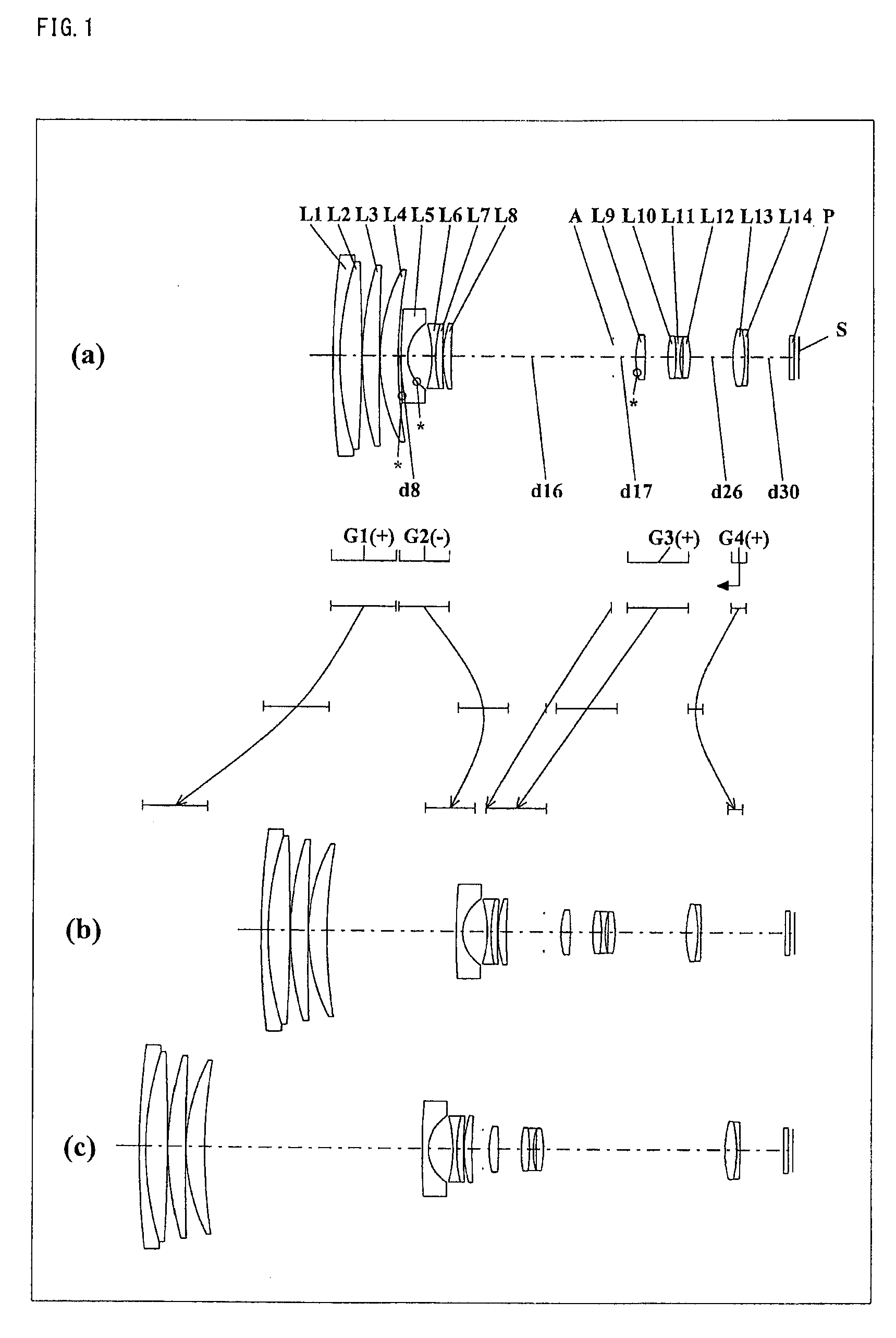
[0278]The zoom lens system of Numerical Example 1 corresponds to Embodiment 1 shown in FIG. 1. Table 1 shows the surface data of the zoom lens system of Numerical Example 1. Table 2 shows the aspherical data. Table 3 shows various data.
TABLE 1(Surface data)Surface numberrdndvdObject surface∞ 1156.317001.250001.9036631.3 258.664000.010001.5673242.8 358.664004.105001.4874970.4 4−372.718000.15000 559.139003.181001.4970081.6 6514.429000.15000 734.995003.431001.4970081.6 895.59400Variable 9*5000.000001.200001.8047041.010*7.362004.6370011−21.172000.700001.7725049.61225.975000.010001.5673242.81325.975001.225001.9459518.01472.482000.160001520.668001.484001.9228620.91687.78800Variable17 (Diaphragm)∞Variable18∞1.2000019*14.645001.772001.5833259.120−54.553004.254002120.589001.536001.6031160.722−27.819000.010001.5673242.823−27.819000.700001.8061033.32414.188000.5520025119.994001.375001.4970081.626−17.32100Variable2720.411002.163001.6031160.728−25.371000.010001.5673242.829−25.371000.600001.71736...
PUM
 Abstract
Description
Claims
Application Information
 - R&D
- Intellectual Property
- Life Sciences
- Materials
- Tech Scout
- Unparalleled Data Quality
- Higher Quality Content
- 60% Fewer Hallucinations
Browse by: Latest US Patents, China's latest patents, Technical Efficacy Thesaurus, Application Domain, Technology Topic, Popular Technical Reports.
© 2025 PatSnap. All rights reserved.Legal|Privacy policy|Modern Slavery Act Transparency Statement|Sitemap|About US| Contact US: help@patsnap.com