
Filter arrangement and methods

a filter and filter technology, applied in the field of filter construction, can solve problems such as cost increas

Active Publication Date: 2011-03-24
DONALDSON CO INC
View PDF25 Cites 39 Cited by
  • Summary
  • Abstract
  • Description
  • Claims
  • Application Information

AI Technical Summary

Benefits of technology

[0008]Another aspect includes methods for operating and servicing. Preferred methods include constructions configured according to principles described herein.

Problems solved by technology

This caused an increase in cost.

Method used


Image

  • Filter arrangement and methods
  • Filter arrangement and methods
  • Filter arrangement and methods

Examples


Embodiment Construction

[0037]Reference will now be made in detail to exemplary aspects of the present invention that are illustrated in the accompanying drawings. Wherever possible, the same reference numbers will be used throughout the drawings to refer to the same or like parts.

[0038]A. FIG. 1, System of Use

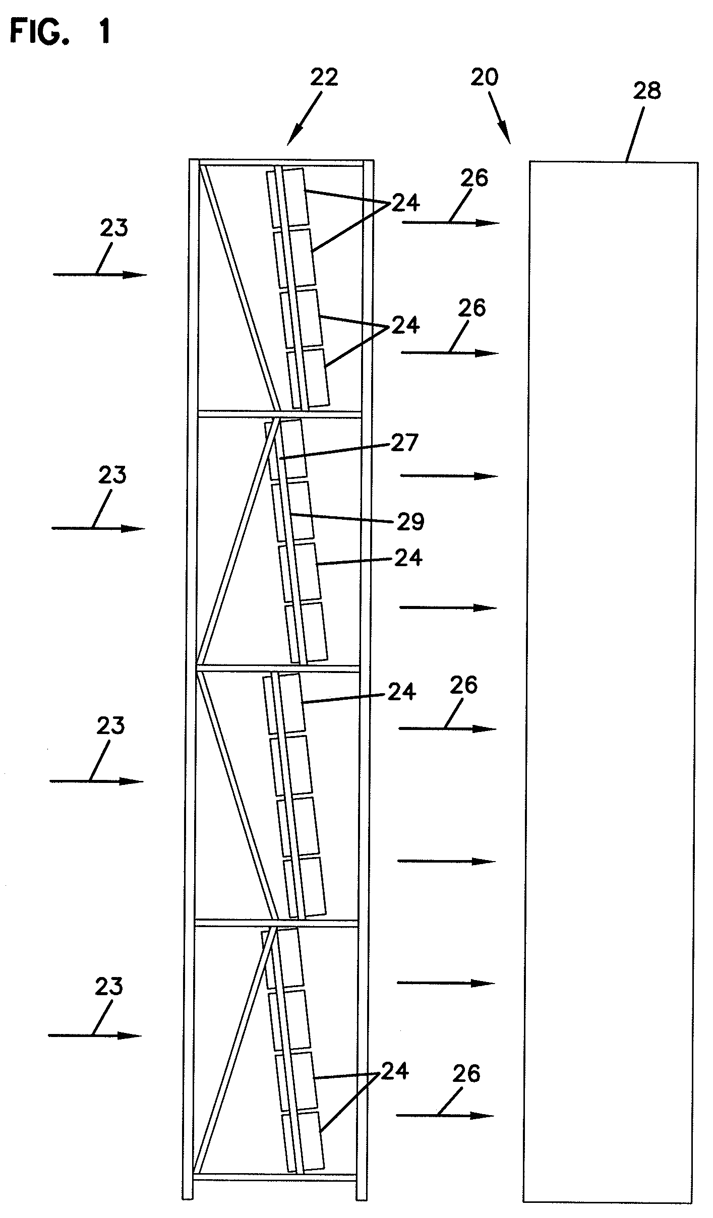
[0039]The air filter elements and constructions disclosed herein are usable in a variety of systems. FIG. 1 depicts one particular system, in this case, a gas turbine system schematically at 20.

[0040]In FIG. 1, airflow is shown drawn into an air intake system 22 at arrows 23. The air intake system 22 includes a plurality of air filter elements 24 generally held in a tube sheet 27 having a plurality of apertures 29. In preferred systems, the tube sheet 27 will be constructed to hold the filter elements 24 at an angle, relative to a vertical axis. Preferred angles will be between 5-25°, for example, about 7°. This permits liquid to drain from the filter elements 24 when the system 20 is not operating.

[...


PUM

PropertyMeasurementUnit
Radiusaaaaaaaaaa
Radiusaaaaaaaaaa

Abstract

A filter element includes a single seamless media pack having first and second opposite ends and first and second lateral sides extending between the first and second ends. The media pack also has pleats extending between the first and second ends and a first cross-section defined between the first and second lateral sides. The first cross-section having at least one outward projection that defines an internal radius of at least ¼ inch wherein a plurality of pleats of the media pack are fanned around the internal radius. A first end cap is secured to the first end of the media pack while a second end cap secured to the second end of the media pack. Additionally, a frame member is secured to the first end cap, second end cap, the first lateral side, and the second lateral side. A pre-filter is usable with described filter arrangements.

Description

CROSS-REFERENCE TO RELATED APPLICATION[0001]This application claims priority under 35 U.S.C. §119(e) to U.S. provisional patent application 61 / 220,107 filed Jun. 24, 2009, incorporated herein by reference.TECHNICAL FIELD[0002]This disclosure describes filter constructions for filtering fluids, such as gas or liquid. In particular, this disclosure describes a filter element comprising a seamless media pack, a housing, and methods particularly useful with gas turbine systems.BACKGROUND[0003]Gas turbine systems are useful in generating electricity. These types of systems are particularly convenient in that they can be constructed quickly; they are also desirable because they produce fewer harmful emissions than coal or oil based turbine systems. Gas turbines utilize air for combustion purposes. Due to the precision moving parts in these types of systems, the combustion air needs to be clean. To ensure clean air for combustion, air filters have been used to clean the air taken into the ...

Claims


Application Information

Patent Timeline
IPC IPC(8): B01D46/52B31F1/20
CPCB01D46/103B01D46/125B01D46/522Y10T29/49826B01D46/525Y10T156/1025B01D46/0001B01D46/0031B01D46/121
Inventor HANDLEY, MICHAELRENWART, DOMINIQUENICHOLS, BENJAMINVANORMELINGEN, HERMANVANDERLINDEN, JIMMYSPORRE, TIMOTHY
Owner DONALDSON CO INC
Features
  • Generate Ideas
  • Intellectual Property
  • Life Sciences
  • Materials
  • Tech Scout
  • Unparalleled Data Quality
  • Higher Quality Content
  • 60% Fewer Hallucinations
Learn More