
Brushless DC motor

a brushless dc motor and motor shaft technology, applied in the direction of stator/rotor body manufacturing, other domestic objects, applying solid insulation, etc., can solve the problems of limited lubrication contained in the bushing, use up, easy damage to the bushing and sha

Active Publication Date: 2011-03-24
STACKPOLE INT POWDER METAL LTD
View PDF7 Cites 6 Cited by
  • Summary
  • Abstract
  • Description
  • Claims
  • Application Information

AI Technical Summary

Benefits of technology

The present invention provides a brushless direct current motor for use in a HVAC system. The motor includes a stator and a rotor. The stator has a stator core and field windings, while the rotor has a shaft and at least one permanent magnet. The bushing is a monolithic construction with two journal portions and one middle portion, and the middle portion has a larger inner diameter than the shaft. The rotor also has a housing and a baffle press-fitted on the output end of the shaft. The stator also has a bushing holder with a recess for receiving the baffle. The motor is designed to be lubricated with lubricant and to prevent moisture and dust from entering through the gap between the shaft and the journal portions. The method of producing the bushing involves making a semi-finished bushing body, sintering it, impregnating it with oil, and using a mold press to compress the end portions of the bushing body. The technical effects of the invention include improved performance and efficiency of the motor, reduced noise, and improved durability.

Problems solved by technology

However, the lubrication contained in the bushing is limited and is used up over time.
In addition, moisture or dust in the air may permeate inside the bushing through the gap between the shaft and the bushing so that the bushing and shaft are easily damaged.

Method used


Image

  • Brushless DC motor
  • Brushless DC motor
  • Brushless DC motor

Examples


Embodiment Construction

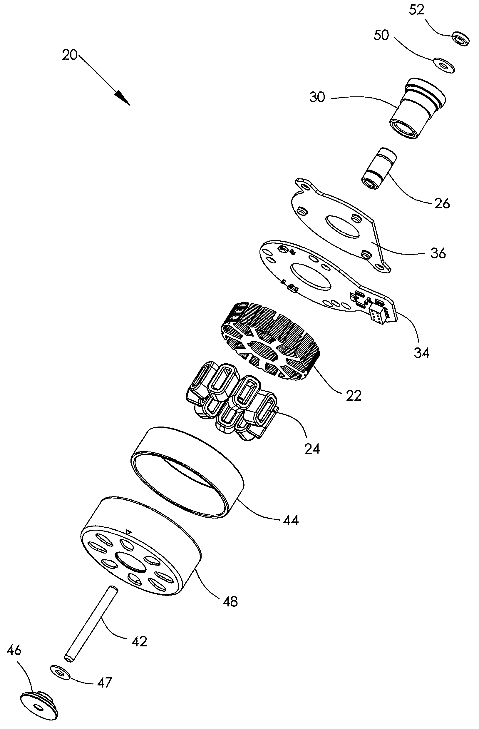
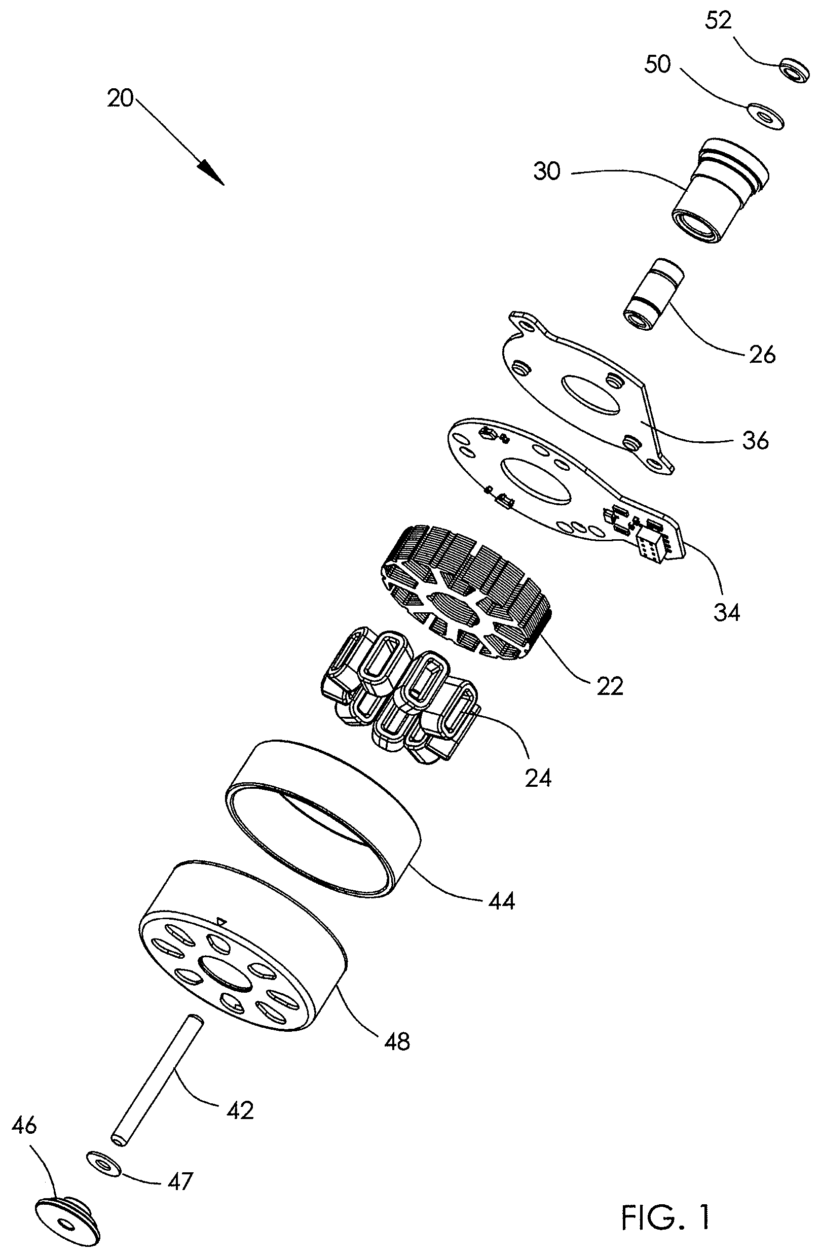
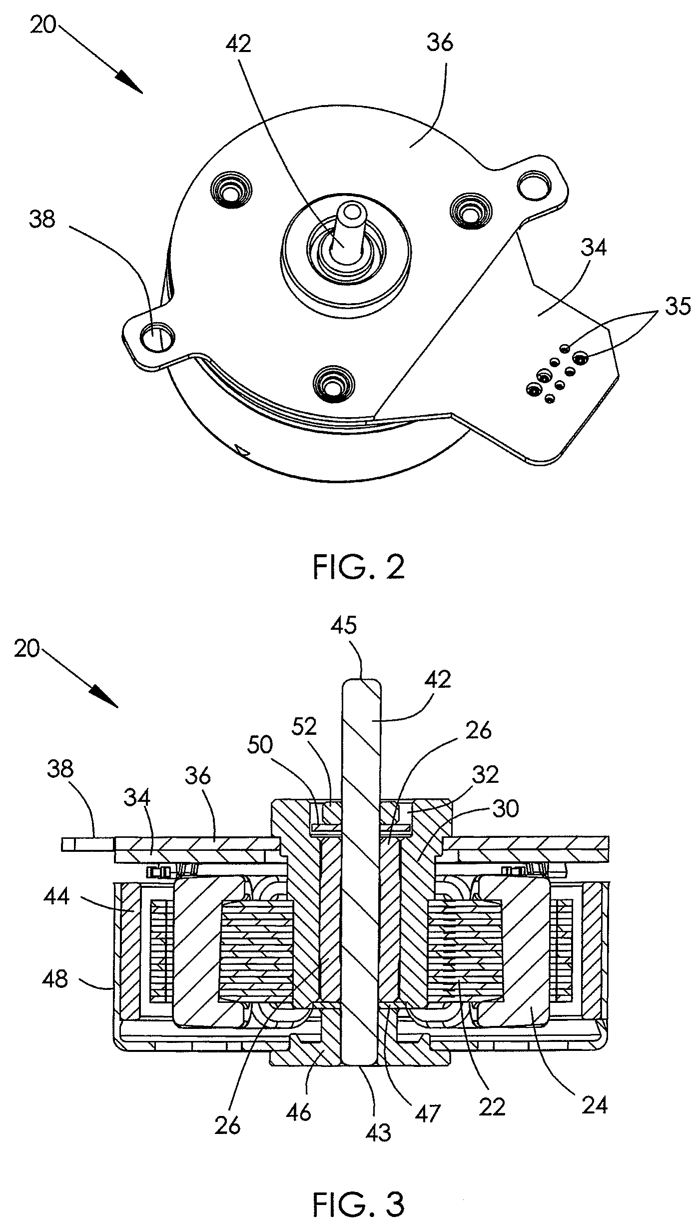
[0020]A BLDC motor for HVAC systems according to the preferred embodiment of the present invention comprises an inner stator and an outer rotor. The stator comprises a stator core 22 and field windings 24 wound onto the stator core 22. The rotor comprises a shaft 42, a housing 48 fixed to the shaft and ring shaped permanent magnet 44 fixed to the housing 48 to rotate with the shaft 42. The rotor is rotatably mounted to the stator with the magnet 44 confronting the field windings 24. The stator includes a bushing 26 which supports the shaft 42 so as to permit the rotor to rotate with respect to the stator.

[0021]The bushing 26 as shown in detail in FIG. 4, comprises a middle portion 262 and two journal portions 264 that are integrally formed at respective ends of the middle portion 262. The two journal portions 264 make sliding contact with the shaft 42 to support the shaft 42, while the middle portion 262 has an inner diameter (ID) which is larger than the outer diameter (OD) of the ...


PUM

PropertyMeasurementUnit
inner diameteraaaaaaaaaa
outer diameteraaaaaaaaaa
outer diametersaaaaaaaaaa

Abstract

A brushless direct current motor for use in a HVAC system, has a stator and a rotor rotatably mounted to the stator. The stator has a stator core, field windings wound on the stator core and a bushing. The rotor has a shaft rotatably supported by the bushing and adapted to connect with a valve adjuster of the HVAC system. The rotor also has at least one permanent magnet fixed with respect to the shaft. The bushing is a monolithic construction with two journal portions and one middle portion. The two journal portions support the shaft and are formed at respective axial ends of the middle portion. The middle portion has an inner diameter larger than an outer diameter of the shaft at portions corresponding to the middle portion, so as to form a gap between the middle portion and the shaft.

Description

CROSS REFERENCE TO RELATED APPLICATIONS[0001]This non-provisional patent application claims priority under 35 U.S.C. §119(a) from Patent Application No. 200910190477.X filed in The People's Republic of China on Sep. 18, 2009.FIELD OF THE INVENTION[0002]This invention relates to a brushless direct current motor and in particular, to a brushless direct current motor for use in heating, ventilating and air-conditioning systems.BACKGROUND OF THE INVENTION[0003]Brushless direct current motors, also known as BLDC motors, are widely used in heating, ventilating and air-conditioning systems, also known as HVAC systems. For example, a BLDC motor is used to control a valve to regulate the amount of air flow. A traditional BLDC motor comprises a rotatable shaft which is supported by two separate bushings. The term “bushing”, as used in this specification, including the appended clams, refers to a self-lubricating sleeve bearing, especially an oil-impregnated sintered bronze sleeve bearing. How...

Claims


Application Information

Patent Timeline
Patent Type & Authority Applications(United States)
IPC IPC(8): H02K5/167B23P17/00
CPCH02K5/1677Y10T29/49012H02K5/10Y10T29/49668
Inventor CHAI, JIEHE, WAN MEISHI, HONG JIAN
Owner STACKPOLE INT POWDER METAL LTD
Learn More