Method for Enlarging Toner Transfer Window in EP Imaging Device and Transfer Station Employing the Method

a technology of ep imaging and toner transfer, which is applied in the direction of electrographic process apparatus, instruments, optics, etc., can solve the problems of inability to achieve print artifacts, inability to achieve future transfer steps, and almost always breakdown, so as to improve overtransfer performance and prevent premature paschen breakdown , the effect of high dielectric breakdown strength

Active Publication Date: 2011-03-24
LEXMARK INT INC
View PDF9 Cites 0 Cited by
  • Summary
  • Abstract
  • Description
  • Claims
  • Application Information

AI Technical Summary

Benefits of technology

[0011]The present invention, which is concerned with the aforementioned high end of the transfer window, meets this need by providing an innovation in which a thin polymer coating layer with high dielectric breakdown strength is applied to a transfer nip defining element in an imaging device for improved overtransfer performance. The coating is applied as a surface layer to one of the elements at the transfer nip. In such manner it will prevent premature Paschen breakdown and increase transfer window size by increasing the electrical voltage at which overtransfer related defects occur and therefore transfer robustness, thereby increasing the operating window. Such layer of thin polymer coating needs to be applied to one or more elements at the transfer nip that can bleed off electrical charge build up as the layer is used as a boundary to current flow and not as a capacitor itself. Such element(s) may be the outer surface of a backup or transfer roll or the inside surface of the transfer or transport belt having a specified range of surface resistivity. The high dielectric breakdown strength of such layer of thin polymer coating is determined by its thickness and material composition.

Problems solved by technology

Transfer robustness is frequently measured as the amount of voltage between the lowest voltage where acceptable transfer occurs because sufficient electric field has been built to move toner, and the highest voltage at which acceptable printing still occurs before Paschen breakdown causes undesirable print artifacts.
Breakdown almost always happens in the air gaps of the imaging device nip.
Electrostatic discharge after the nip is the least severe of these as the result is to add charge to toner already transferred which might make future transfer steps more difficult.
Electrostatic discharge in the nip or before the nip can cause reversal of charge on toner or movement of toner which will show up as a print defect.
Thus, depending on the location of the breakdown, various print defects will likely be present in the page, which would make the print unacceptable.
All of these improvements have made print quality significantly better in current color (multi-toner-layer) EP imaging devices however some issues remain.
Imaging devices also tend to get too much non-uniform electric field in the transfer nip which causes the system to go into overtransfer pre-maturely.
This means that print quality degrades significantly, and so operating windows are compressed or disappear.

Method used


Image

  • Method for Enlarging Toner Transfer Window in EP Imaging Device and Transfer Station Employing the Method
  • Method for Enlarging Toner Transfer Window in EP Imaging Device and Transfer Station Employing the Method

Examples


Embodiment Construction

[0017]The present invention now will be described more fully hereinafter with reference to the accompanying drawings, in which some, but not all embodiments of the invention are shown. Indeed, the invention may be embodied in many different forms and should not be construed as limited to the embodiments set forth herein; rather, these embodiments are provided so that this disclosure will satisfy applicable legal requirements. Like numerals refer to like elements throughout the views.

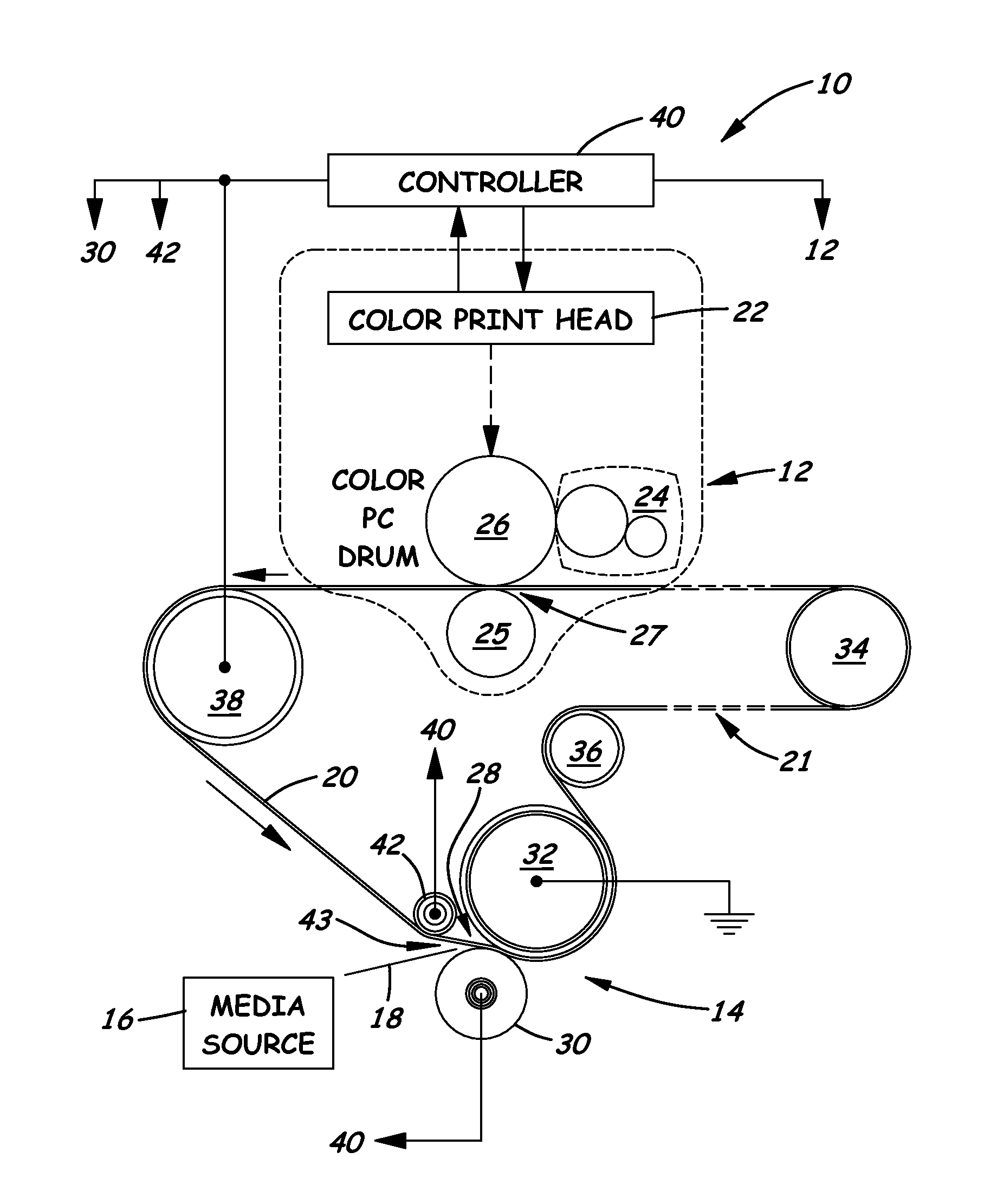
[0018]Referring to FIG. 1, there is schematically illustrated in simplified form an exemplary embodiment of a color EP imaging device 10 to which the present invention may be applied. The imaging device 10 is a two transfer system which includes, in part, a plurality of first transfer color imaging forming stations 12 (only one being shown), a second transfer station 14, a media source 16 for feeding one at a time a media sheet 18 of paper, for instance, to the second transfer station 14, and an intermed...


PUM


Abstract

A transfer station for toner transfer in an electrophotographic imaging device includes an endless transfer belt transported about an endless path through the imaging device, a transfer roll adjacent one surface of the transfer belt, and a backup roll adjacent an opposite surface of the transfer belt opposite from the transfer roll such that the transfer roll and backup roll form a transfer nip effecting transfer of toner. For the purpose of improved overtransfer performance, an outer layer of a thin polymer coating is applied to at least one of the transfer belt and the rolls so as to be located within the transfer nip with transfer of toner. The polymer layer has a thickness from about 5 μm to about 200 μm, surface resistivity from about 1E08 to about 1E12 Ohm/cm and breakdown strength greater than 500 V.

Description

CROSS REFERENCES TO RELATED APPLICATIONS[0001]This patent application is related to the subject matter of co-pending U.S. patent application Ser. No. 12 / 544,650, Docket No. 2007-0373.01 filed Aug, 20, 2009, assigned to the assignee of the present invention. The entire disclosure of this patent application is hereby incorporated herein by reference.BACKGROUND[0002]1. Field of the Invention[0003]The present invention relates generally to electrophotographic (EP) imaging devices and, more particularly, to a method for enlarging a transfer window in an EP imaging device for toner transfer and also to a transfer station employing the method in which a layer of a thin polymer coating with high dielectric breakdown strength applied to a transfer nip defining element improves transfer efficiency and print quality.[0004]2. Description of the Related Art[0005]An electrophotographic (EP) imaging device uses electrostatic voltage differentials to promote the transfer of toner from component to ...

Claims


Application Information

Patent Timeline
Patent Type & Authority Applications(United States)
IPC IPC(8): G03G15/16
CPCG03G2215/1623G03G15/162
Inventor HULLMAN, DAVID WILLIAMKEMP, BRANDON ALDENMURRELI, NIKO JAYNELSON, RYAN JAMESWHITNEY, JULIE ANN GORDON
Owner LEXMARK INT INC
Why Eureka
Try Eureka