Electroencephalogram interface system

a technology of electroencephalogram and interface, which is applied in the field of interface (electroencephalogram interface) system, can solve the problems of affecting the user's hand-free feature, affecting the user's comfort, so as to achieve stable electrode contact, increase the clamping against the user, and avoid the effect of increasing the burden on the user

Inactive Publication Date: 2011-03-24
SOVEREIGN PEAK VENTURES LLC
View PDF9 Cites 52 Cited by
  • Summary
  • Abstract
  • Description
  • Claims
  • Application Information

AI Technical Summary

Benefits of technology

[0017]The present invention has been made in view of the above problems, and an objective thereof is to provide an electroencephalogram interface system which ensures stable electrode contact, without increasing a user's burden through increased clamping against the user.

Problems solved by technology

However, if the aforementioned physical device manipulations are required when manipulating a device whose body has a small size and which is characterized to be handsfree, e.g., an eyeglass-type HMD, the handsfree feature will be undermined, thus being ineffective.
However, since there is a strong need for downsizing any wearable device to be worn on the face such as an HMD, it is highly likely that the portion extending across the head (as in headphones) will be considered unnecessary in the future.
Moreover, a shape extending across the head is aesthetically poor, and may make the hair messy when worn, and thus is not an idealistic HMD shape of the future.
However, an HMD is a device which is frequently put on or taken off, rather than being perpetually worn.
Therefore, it will be a great burden on the user to have to separately wear a device in addition to the HMD.
However, an increased pressuring on the user will lead to an increased burden on the user associated with clamping, which makes long hours of wearing difficult.

Method used


Image

  • Electroencephalogram interface system
  • Electroencephalogram interface system
  • Electroencephalogram interface system

Examples


embodiment 1

[0076]FIG. 4 shows the functional block construction of an electroencephalogram interface system 1 according to the present embodiment. FIG. 5 shows an exemplary device shape of the electroencephalogram interface system 1. FIG. 6 shows an exemplary hardware construction of the electroencephalogram interface system 1.

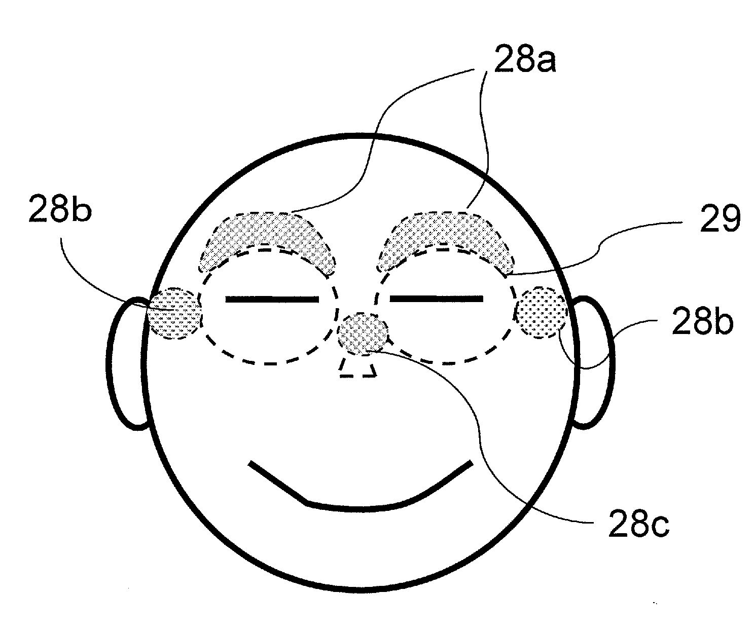
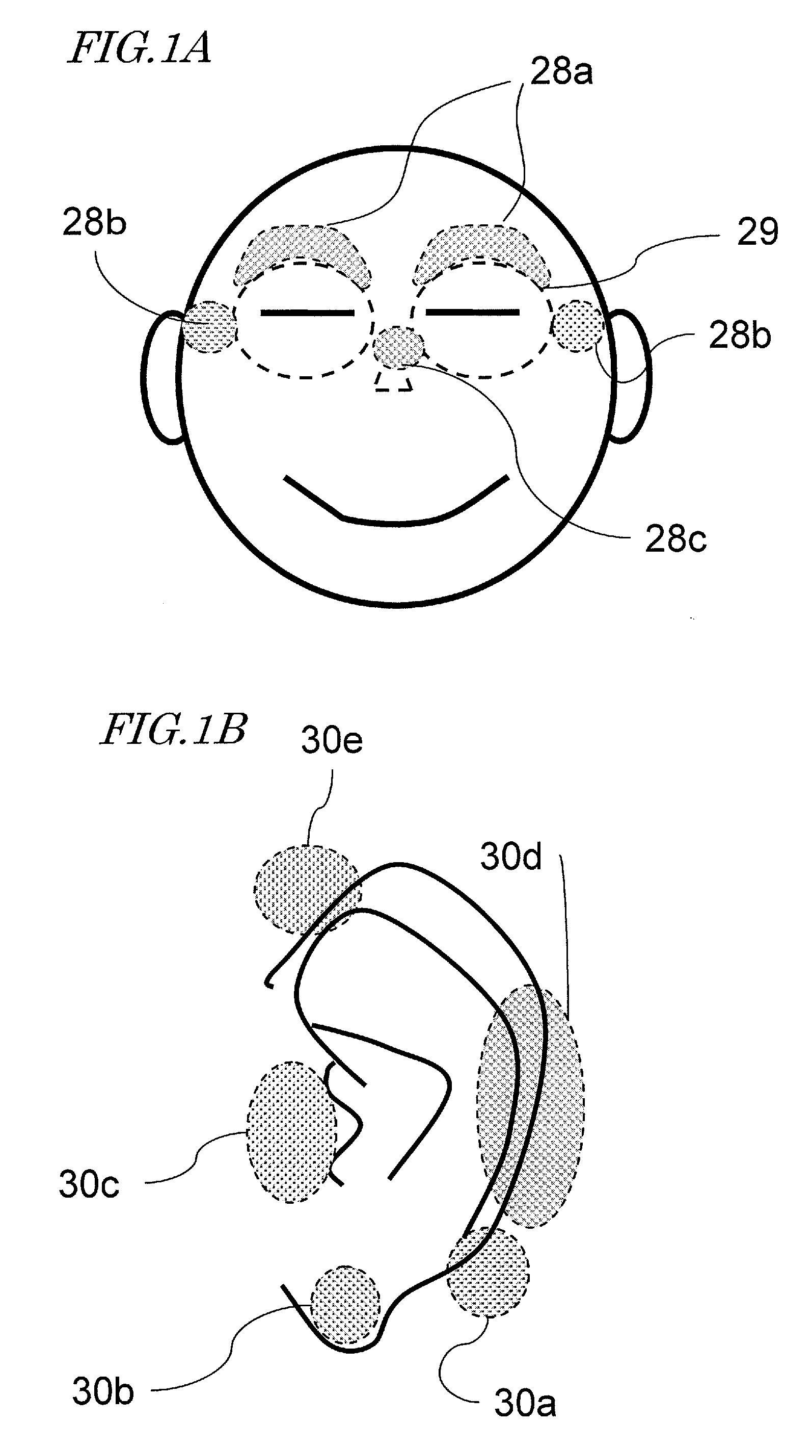
[0077]As shown in FIG. 4, the electroencephalogram interface system 1 includes an ear electrode portion 11, a facial electrode portion 12, an electroencephalogram measurement and determination section 13, and an output section 14. In FIG. 4, the user 10 is illustrated for convenience of explanation.

[0078]As shown in FIG. 5, the names of respective portions of an HMD are similar to those of eyeglasses. Hereinafter, any portion that hangs on an ear of the user 10 to fix the HMD body will be referred to as an “endpiece portion 21”. Any portion that comes in contact with the nose of the user 10 to support the HMD body will be referred to as a “nose pad portion 24”. A portion...

embodiment 2

[0118]In Embodiment 1, as shown in FIG. 5, FIG. 7, FIG. 8, and FIG. 10, a construction was illustrated where endpiece portions are hung on the ear-root superior portions so that the facial electrode portion(s) 12 which is in contact with the face of the user 10 supports the HMD mass, thus fixing the HMD in a manner of sandwiching the head with the endpiece portions and the facial electrode portion(s) 12. In particular, the HMD examples of FIG. 7 and FIG. 8 utilize a difference between the distance α from an ear-root superior portion to the upper end of an eye-socket upper edge and the distance β from the ear-root superior portion to the lower end of the eye-socket upper edge as shown in FIG. 9, thus fixing the HMD in a manner of sandwiching the head of the user 10.

[0119]However, the shapes of the face and the head differ from person to person, and it is also possible for the distances α and β shown in FIG. 9 to differ depending on each individual. Therefore, sandwiching of the user ...


PUM


Abstract

An eyeglass-type electroencephalogram interface system is worn on the head of a user. The system includes: an output section for presenting a visual stimulation to the user; an ear electrode portion disposed at a position coming in contact with an ear of the user when the system is worn; a facial electrode portion disposed at a position coming in contact with the face below a straight line connecting an external canthus and an internal canthus of an eye of the user, such that the mass of the system is supported at the position, when the system is worn; and an electroencephalogram measurement and determination section for measuring an event-related potential on the basis of a potential difference between the ear electrode portion and the facial electrode portion based on the visual stimulation being presented by the output section as a starting point.

Description

[0001]This is a continuation of International Application No. PCT / JP2010 / 000197, with an international filing date of Jan. 15, 2010, which claims priority of Japanese Patent Application No. 2009-009179, filed on Jan. 19, 2009, the contents of which are hereby incorporated by reference.BACKGROUND OF THE INVENTION[0002]1. Field of the Invention[0003]The present invention relates to an interface (electroencephalogram interface) system for allowing a device to be manipulated by utilizing an electroencephalogram.[0004]2. Description of the Related Art[0005]In recent years, wearable devices such as head-mount displays (hereinafter also referred to as “HMDs”) are gaining prevalence due to decreases in the size and weight of devices. Normally, as interfaces of devices, methods such as pressing a button, moving a cursor to make a decision, and manipulating a mouse while looking at a screen have been used. However, if the aforementioned physical device manipulations are required when manipula...

Claims


Application Information

Patent Timeline
Patent Type & Authority Applications(United States)
IPC IPC(8): A61B5/0476
CPCA61B5/0478G06F3/015A61B5/6803A61B5/04842A61B5/1103A61B5/04012A61B5/291A61B5/316A61B5/378
Inventor TERADA, YOSHIHISAMORIKAWA, KOJI
Owner SOVEREIGN PEAK VENTURES LLC
Why Eureka
Try Eureka