

Parallel mechanism and moveable linkage thereof
- Summary
- Abstract
- Description
- Claims
- Application Information
AI Technical Summary
Benefits of technology
Problems solved by technology
Method used
Image

Examples
Embodiment Construction
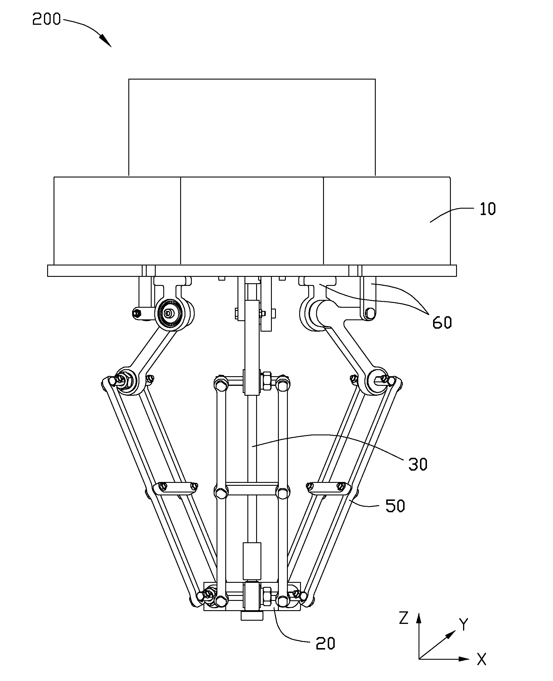
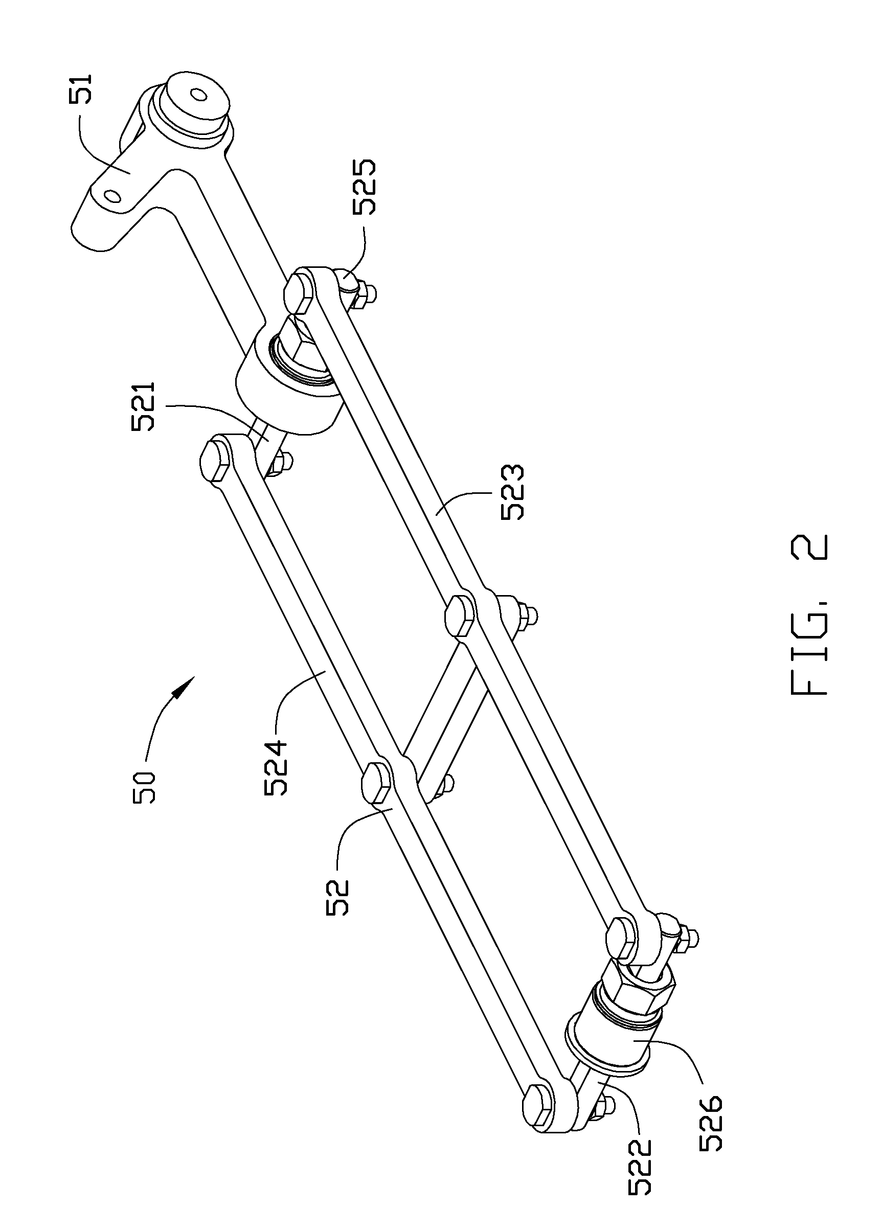
[0013]Referring to FIG. 1, an embodiment of a parallel mechanism 200 is a four freedom parallel mechanism, and includes a stationary platform 10, a movable platform 20, a rotatable linkage 30, three movable linkages 50 connecting the stationary platform 10 and the movable platform 20, and four driving modules 60. The rotatable linkage 30 and the movable linkages 50 are movably connected to the stationary platform 10 by the driving modules 60.
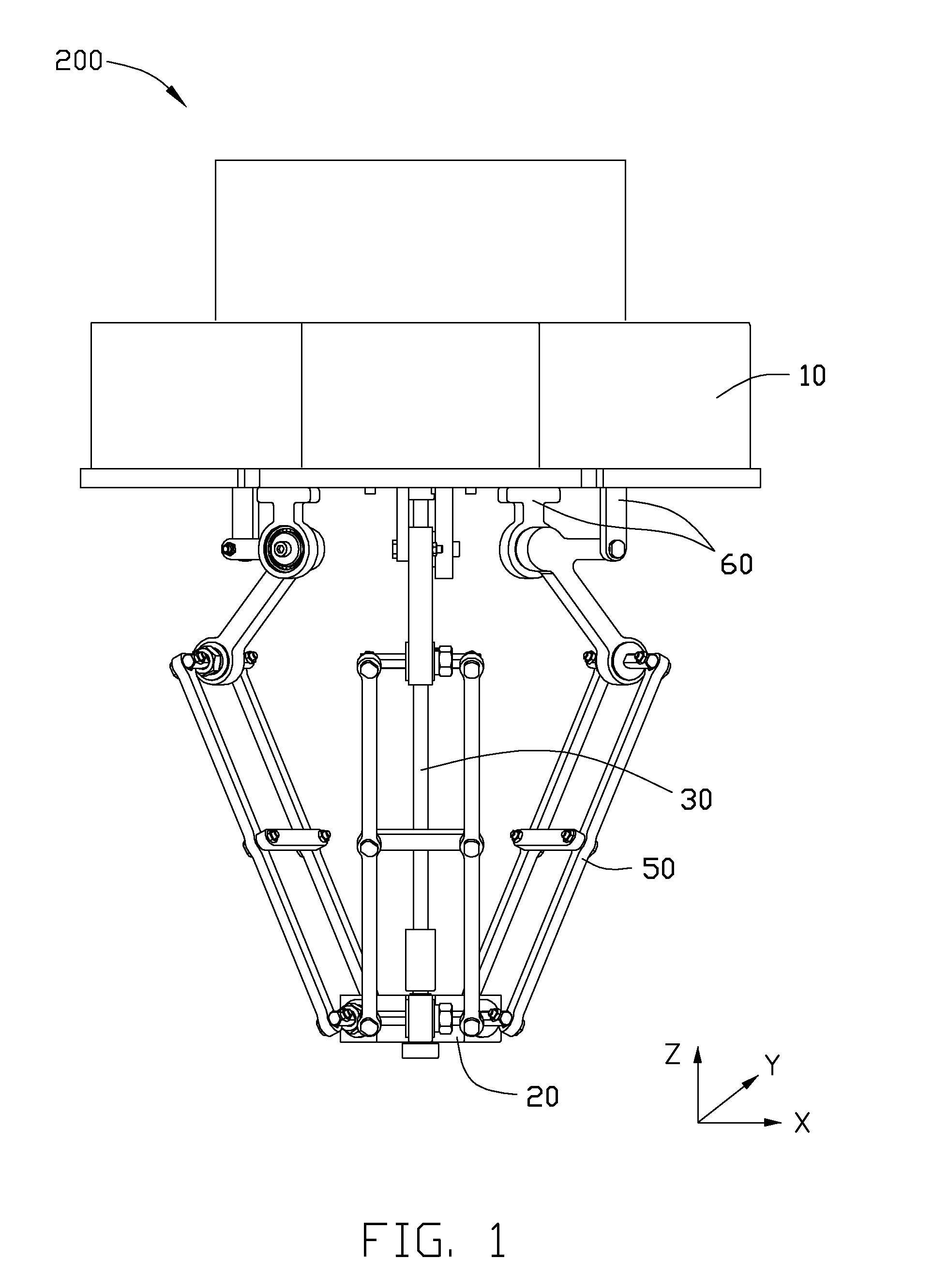
[0014]Referring also to FIGS. 2 and 3, each moveable linkage 50 includes a swing arm 51 and a four-link structure 52. The four-link structure 52 includes a first connection shaft 521, a second connection shaft 522, a first link bracket 523, a second link bracket 524, a plurality of connection modules 525, and two pivotal modules 526. The first connection shaft 521 is rotatably connected to the swing arm 51, the second connection shaft 522 is rotatably connected to the movable platform 20. The first and second link brackets 523, 524 are rotatably...
PUM
 Abstract
Description
Claims
Application Information