Leg-portion attachment structure and image forming apparatus provided therewith

Active Publication Date: 2011-03-31
KYOCERA DOCUMENT SOLUTIONS INC
View PDF16 Cites 12 Cited by
  • Summary
  • Abstract
  • Description
  • Claims
  • Application Information

AI Technical Summary

Benefits of technology

[0037]With the configuration, the present invention provides an image forming apparatus provided with a leg-portion attachment structure, the leg-portion attachment structure being capable of reliably supporti

Problems solved by technology

However, interposition of the coil springs or the rubber blocks between the apparatus main body and the casters as disclosed in the above-mentioned technologies has led to problems of upsizing and increase in cost of the apparatus.
Further, load of the apparatus main body is much larger in the case of an image forming apparatus such as a large copier, and hence a hig

Method used


Image

  • Leg-portion attachment structure and image forming apparatus provided therewith
  • Leg-portion attachment structure and image forming apparatus provided therewith
  • Leg-portion attachment structure and image forming apparatus provided therewith

Examples


first embodiment

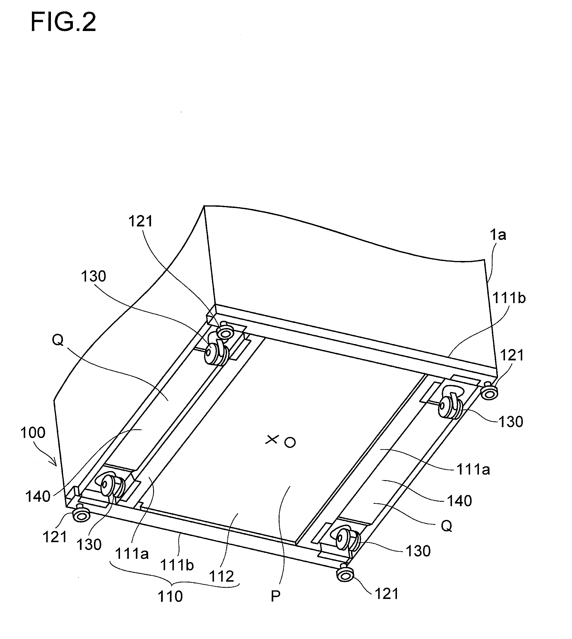
[0055]FIG. 2 is a perspective view from a floor surface side, illustrating the leg-portion attachment structure 100 according to a first embodiment of the present invention.

[0056]The leg-portion attachment structure 100 includes the support member 110, attachment plates 140, the casters 130, and fixing legs 121. The apparatus main body 1a of the image forming apparatus 1 is mounted onto an upper surface of the support member 110. The casters 130 and the fixing legs 121 are respectively arranged at four corners of the lower surface of the support member 110, the casters 130 being provided rotatably with respect to the support member 110, the fixing legs 121 being provided in a manner of holding the apparatus main body 1a with respect to a floor surface at the time of installation. Note that, in this embodiment, description is made on the premise that the floor surface side of the leg-portion attachment structure 100 is referred to as “lower surface” or “lower side”, and an apparatus ...

second embodiment

[0087]FIG. 6 is a perspective view of a main portion of an attachment plate according to a second embodiment of the present invention. Description is made of an attachment plate different from that in the first embodiment, and description of the same portions as those in the first embodiment is omitted in the following.

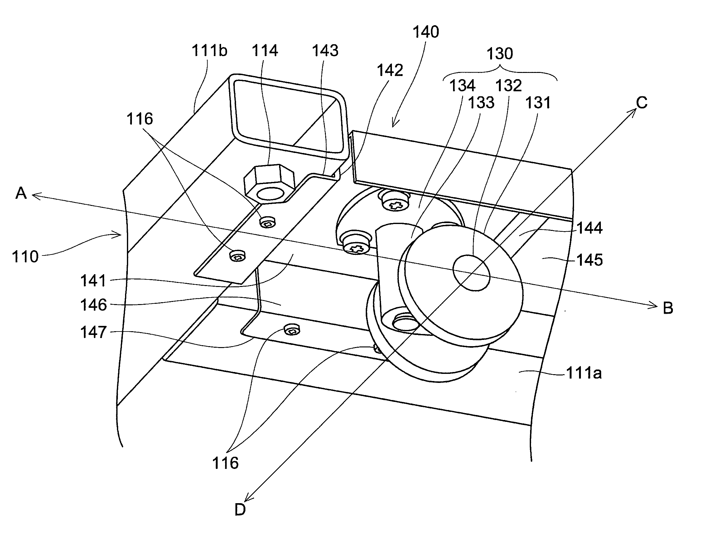
[0088]An attachment plate 240 includes a caster attachment portion 241, a first bent portion 242 formed by downward bending at a right angle of an outer edge in a side direction of the caster attachment portion 241 (direction of the arrows A-B of FIG. 3), and a first coupling portion 243 formed by outward bending at a right angle of a lower end portion of the first bent portion 242. The first coupling portion 243 is firmly attached to a pipe (support member) (not shown) with screws or by spot welding.

[0089]Further, the attachment plate 240 includes a second bent portion 244 formed by downward bending at a right angle of an inner edge in the side direction of the caste...

third embodiment

[0093]FIG. 7 is a schematic partial sectional view taken along the side direction of an attachment plate according to a third embodiment of the present invention. The second bent portions are not provided in the third embodiment.

[0094]An attachment plate 340 includes the following provided on each end side thereof: a caster attachment portion 341, a first bent portion 342 formed by downward bending at a right angle of an outer edge in a side direction of the caster attachment portion 341 (direction of the arrows A-B of FIG. 3), and a first coupling portion 343 formed by outward bending at a right angle of a lower edge of the first bent portion 342. A connecting portion 345 is formed on an inner side of each of the caster attachment portions 341. The connecting portion 345 and the caster attachment portion 341 are formed on the same plane.

[0095]Each of the first coupling portions 343 is firmly attached to the lower surface of the pipe 111b with the screw 116 and the nut 117.

[0096]Whe...


PUM


Abstract

A leg-portion attachment structure (100) includes: a support member (110) having a substantially quadrilateral outer periphery and an upper surface on which an apparatus main body (1a) is mounted; two attachment plates (140) provided at two opposite sides on a lower surface of the support member (110). Each of the attachment plates (140) includes caster attachment portions (141) formed respectively on both end sides in a side direction so that casters (130) are firmly attached, first bent portions (142) formed by bending of outer edges in the side direction of the caster attachment portions (141) at predetermined angles, and first coupling portions (143) that are formed by further outward bending of edges of the first bent portions (142) and are firmly attached to the support member (110).

Description

[0001]This application is based on Japanese Patent Application No. 2009-220913 filed on Sep. 25, 2009, the contents of which are hereby incorporated by reference.BACKGROUND OF THE INVENTION[0002]1. Field of the Invention[0003]The present invention relates to a leg-portion attachment structure for movably supporting to-be-mounted main bodies of an image forming apparatus, an electric / electronic apparatus, and the like, and relates to an image forming apparatus provided with the leg-portion attachment structure.[0004]2. Description of Related Art[0005]Some main bodies of image forming apparatuses, electric / electronic apparatuses, and the like are provided with casters. When a heavy image forming apparatus difficult to carry by hand is carried in and out from, for example, an office, or is moved in the office, the image forming apparatus is easily moved by means of the casters.[0006]For example, four casters are respectively provided at four corners of a bottom surface of an apparatus ...

Claims


Application Information

Patent Timeline
IPC IPC(8): B60B33/00F16M11/22
CPCB60B33/0002B60B33/0007B60B33/0018B60B33/0042B60B33/0049B60B33/0057Y10T16/184B60B33/0073Y10T16/204Y10T16/191Y10T16/203Y10T16/18Y10T16/19B60B33/0068
Inventor AOYAMA, YOSHIKI
Owner KYOCERA DOCUMENT SOLUTIONS INC
Why Eureka
Try Eureka