Hemispherical Wedge Valve with Laminar Flow

Inactive Publication Date: 2011-03-31
PROSERV OFFSHORE INC +1
View PDF14 Cites 16 Cited by
  • Summary
  • Abstract
  • Description
  • Claims
  • Application Information

AI Technical Summary

Benefits of technology

[0012]This divides the flow of the fluid at the inlet of the valve into a plurality of parallel flow pa

Problems solved by technology

Non-laminar flow can result in excessive noise, structural failure,

Method used


Image

  • Hemispherical Wedge Valve with Laminar Flow
  • Hemispherical Wedge Valve with Laminar Flow
  • Hemispherical Wedge Valve with Laminar Flow

Examples


Example

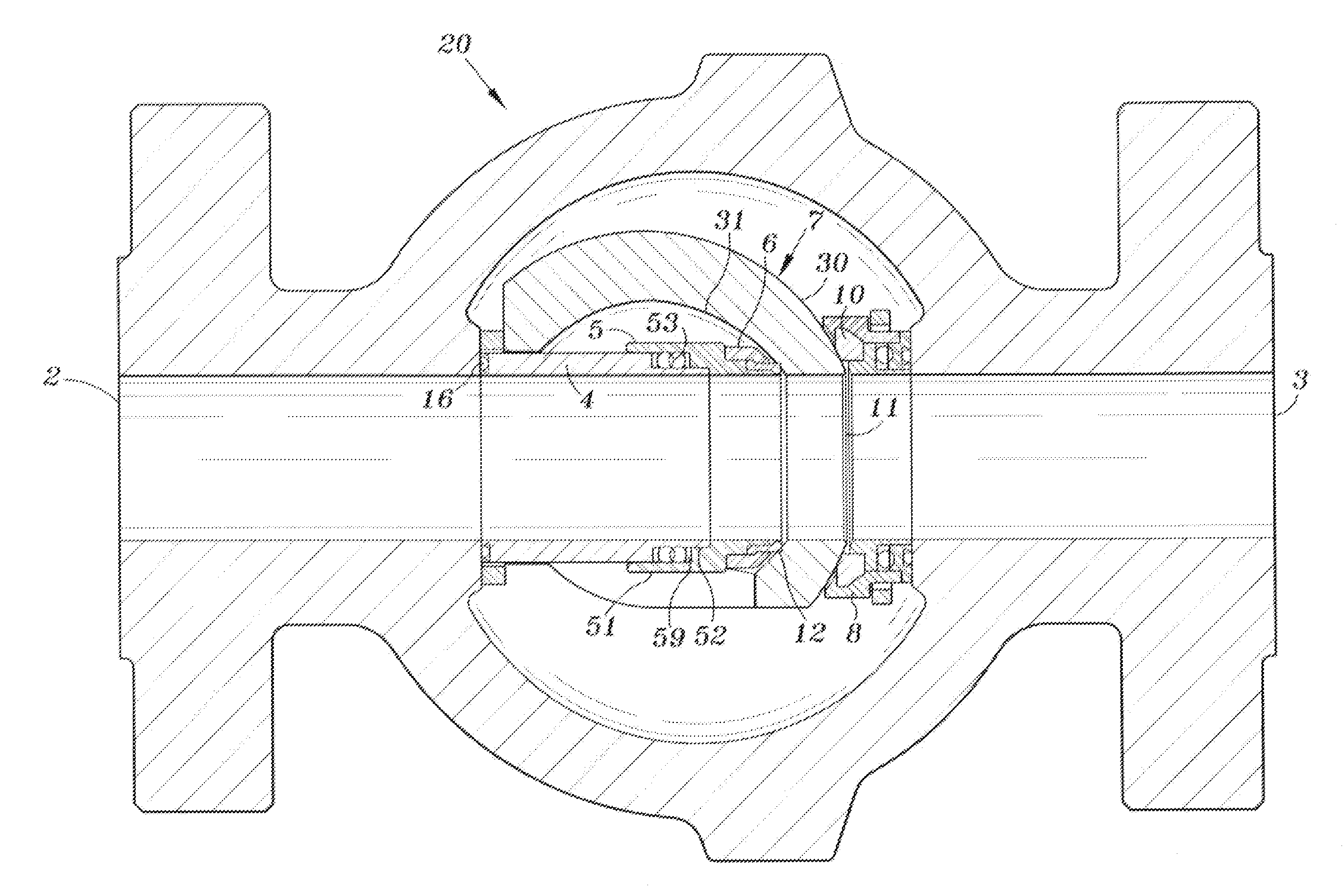
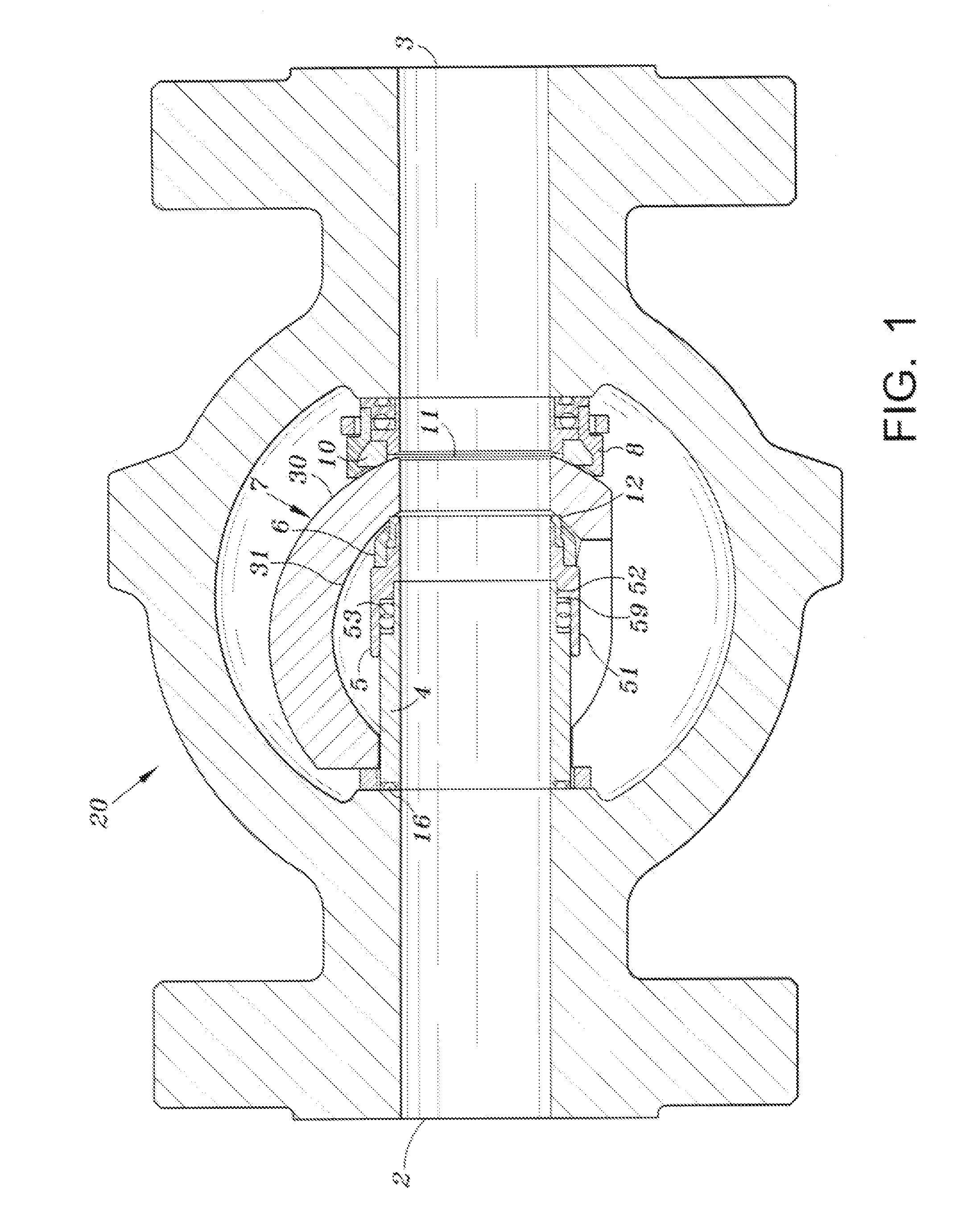
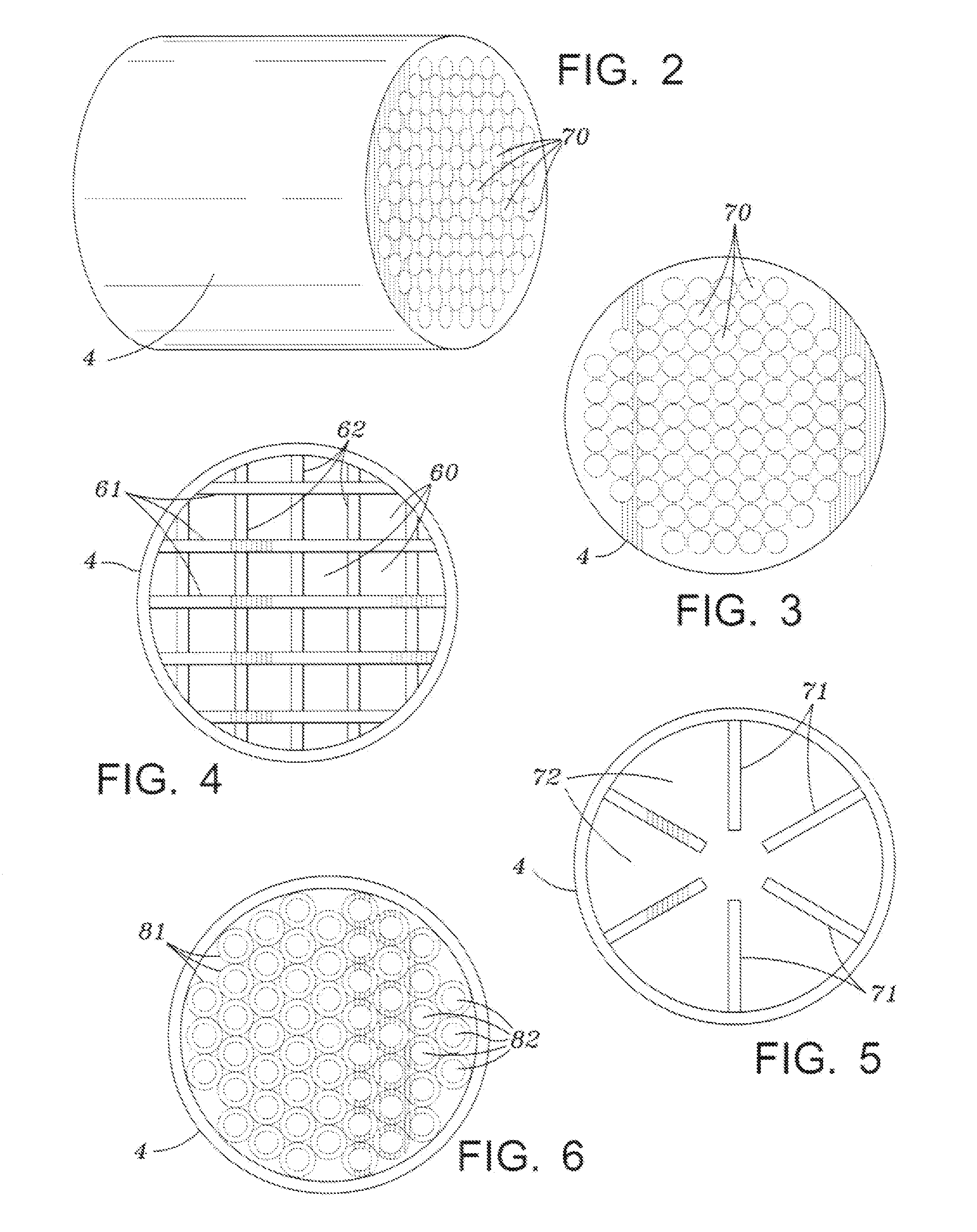
[0019]Referring to FIG. 1, a hemi-wedge valve 20 is shown including an inlet 2, a core section comprising two cylindrical hollow body members 4, 5, and an outlet 3. A hemi-wedge valve element 7 is rotatably mounted in the valve 20. The thickness of the hemi wedge valve element increases from the leading edge to the trailing edge which results in an improved seal. The operation of the wedge is described in detail in U.S. Pat. No. 4,962,911, the contents of which is expressly incorporated herein by reference thereto. In order to maintain laminar flow, a solid valve core member 4 as shown in FIG. 2 that includes a plurality of separate flow paths 70 is provided. The valve also includes various seals 16, 53, 12, 10. Core member 5 includes a first cylindrical portion 51, a first shoulder 59 and a second cylindrical portion 52 that receive complimentary shaped portions on the core member 4. Hemi-wedge valve element 7 includes inner and outer curved surfaces 31 and 30. A downstream valve s...


PUM


Abstract

A valve having a hemispherical wedge closure member and including structure for maintaining laminar fluid flow through the valve body. The laminar fluid flow structure may include a solid core member with a plurality of discrete bores therethrough or a plurality of baffles extending longitudinal through a hollow core member. The laminar flow reduces noise, structural failure, erosion, cavitation, and premature wearing of valve seals and seats.

Description

[0001]This application claims priority to provisional application Ser. No. 61 / 245,896 filed on Sep. 28, 2009BACKGROUND OF INVENTION[0002]1. Field of the Invention[0003]The present invention generally relates to an improved valve of the hemi-wedge type for use in the control of fluids in a pipeline. The valve of the present invention is particularly useful in providing both a tight shutoff of fluids when closed, a high flow when open, and includes a device for providing laminar flow through the valve body when in the open position.[0004]2. Description of Related Art[0005]Ball valves, plug, valves, and the like are well known to those skilled in the art. A common characteristic of these valves is that they may be moved from a full open position to a full closed position through an angle of no more than about ninety (90) degrees.[0006]A simple ball valve comprises a rotatable ball having a bore therethrough corresponding to the fluid flow path, together with a seat for sealing with the...

Claims


Application Information

Patent Timeline
IPC IPC(8): F16K1/54
CPCF16K5/0605F16K47/08F16K5/0621
Inventor ALLEN, STANLEY C.
Owner PROSERV OFFSHORE INC
Why Eureka
Try Eureka