Laminar flow meter
A technology of laminar flowmeter and sheet flow, which is applied in volume measurement, liquid/fluid solid measurement, fluid flow detection by measuring pressure difference, etc. It can solve the problems of poor accuracy of laminar flowmeter and high requirements for working conditions, and achieve measurement The effect of accurate data and elimination of technical bias
- Summary
- Abstract
- Description
- Claims
- Application Information
AI Technical Summary
Problems solved by technology
Method used
Image
Examples
Embodiment 1
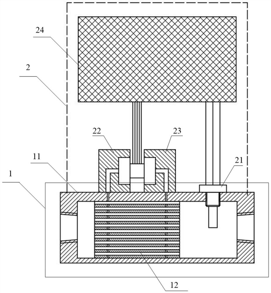
[0024] Such as figure 1 As shown, a laminar flow meter includes: the laminar flow meter includes a fluid detection module 1 and a measurement calculation module 2 placed outside the fluid detection module 1;
[0025] The fluid detection module 1 includes a housing 11, a laminar fluid 12 matched with the housing 11, and the laminar fluid 12 includes a number of stacked laminar flow units;
[0026] Measurement calculation module 2 comprises temperature sensor 21, front pressure sensor 22, rear pressure sensor 23, calculator 24, and calculator 24 is connected with the data end of temperature sensor 21, front pressure sensor 22, rear pressure sensor 23; The detection ends of the sensor 21 , the front pressure sensor 22 and the rear pressure sensor 23 are connected to the fluid detection module 1 .
[0027] The above embodiments are described below. The main element of laminar flowmeter is laminar fluid 12, also known as laminar flow unit, laminar flow element, the main purpose i...
Embodiment 2
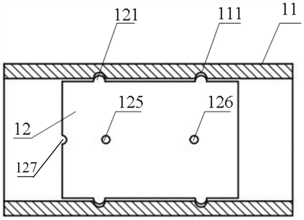
[0030] Such as Figure 1-3 As shown, on the basis of Embodiment 1, this embodiment makes the following improvements: the housing 11 and the laminar fluid 12 that cooperates with the housing 11 are specifically, the two sides of the laminar fluid 12 that are in contact with the housing 11 are respectively provided with convex The housing 11 is provided with a recess 111 at a position corresponding to the protrusion 121 .
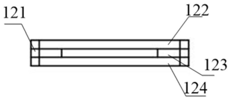
[0031] Since the laminar fluid 12 is formed by overlapping and stacking laminar flow units, it faces the technical problem that the laminar flow units are fixed to each other without displacement. In the prior art, some adhesives are used for bonding, but because the adhesive itself has a thickness, the relevant parameters are not unique and difficult to determine; some are fixed by bolts and nuts, but this method is more common in The case where the laminar fluid separates from the shell. When the laminar fluid is separated from the shell, the fluid will f...
Embodiment 3
[0036] Such as Figure 1-4 As shown, on the basis of the above-mentioned embodiment, the improvement of this embodiment is: the upper flow sheet 122 and the lower flow sheet 124 are both provided with a front pressure measuring hole 125 and a rear pressure measuring hole 126, and the upper flow sheet 122 is provided with a front pressure measuring hole 126. The pressure measuring hole 125 and the rear pressure measuring hole 126 are in the same position as the front pressure measuring hole 125 and the rear pressure measuring hole 126 provided on the lower laminar flow sheet 124, forming a front pressure measuring channel through the upper laminar flow sheet 122 and the lower laminar flow sheet 124 in the vertical direction. hole and the back pressure measurement through hole, the front pressure measurement through hole is connected with the front pressure sensor 22, and the rear pressure measurement through hole is connected with the rear pressure sensor 23.
[0037]The design...
PUM
 Abstract
Description
Claims
Application Information
 - R&D
- Intellectual Property
- Life Sciences
- Materials
- Tech Scout
- Unparalleled Data Quality
- Higher Quality Content
- 60% Fewer Hallucinations
Browse by: Latest US Patents, China's latest patents, Technical Efficacy Thesaurus, Application Domain, Technology Topic, Popular Technical Reports.
© 2025 PatSnap. All rights reserved.Legal|Privacy policy|Modern Slavery Act Transparency Statement|Sitemap|About US| Contact US: help@patsnap.com


