Heat transfer tube and heat exchanger using same

a heat exchanger and heat transfer tube technology, applied in the direction of heat exhanger sealing arrangement, tubular elements, lighting and heating apparatus, etc., can solve the problems of complex and costly plural tube heat exchange step itself, high cost, and water and refrigerant mixing, and achieve the effect of enhancing the heat exchange performance of the heat exchanger

Inactive Publication Date: 2007-08-16
HITACHI CABLE
View PDF2 Cites 33 Cited by
  • Summary
  • Abstract
  • Description
  • Claims
  • Application Information

AI Technical Summary

Benefits of technology

[0028]According to the present invention, it is possible to provide a heat transfer tube for a heat exchanger that is capable of enhancing heat transfer performan

Problems solved by technology

In such a double tube heat exchanger, in the inner tube through which a refrigerant flows, hole formation may be caused by corrosion, which leads to a mixing of the water and refrigerant.
In the heat exchanger disclosed in JP-A-2004-360974, however, there are the problems that the plural-tube-helically-twisting step itself is complicated and costly (twisting a hollow tube that tends to deform (collapse, break, etc.) is not so easy compared to twisting a solid wire), and that the treatment (structure) of the heat exchanger ends, in which the first heat transfer tube and the plural-tube second heat transfer tube are separated from each oth

Method used


Image

  • Heat transfer tube and heat exchanger using same
  • Heat transfer tube and heat exchanger using same
  • Heat transfer tube and heat exchanger using same

Examples


first embodiment

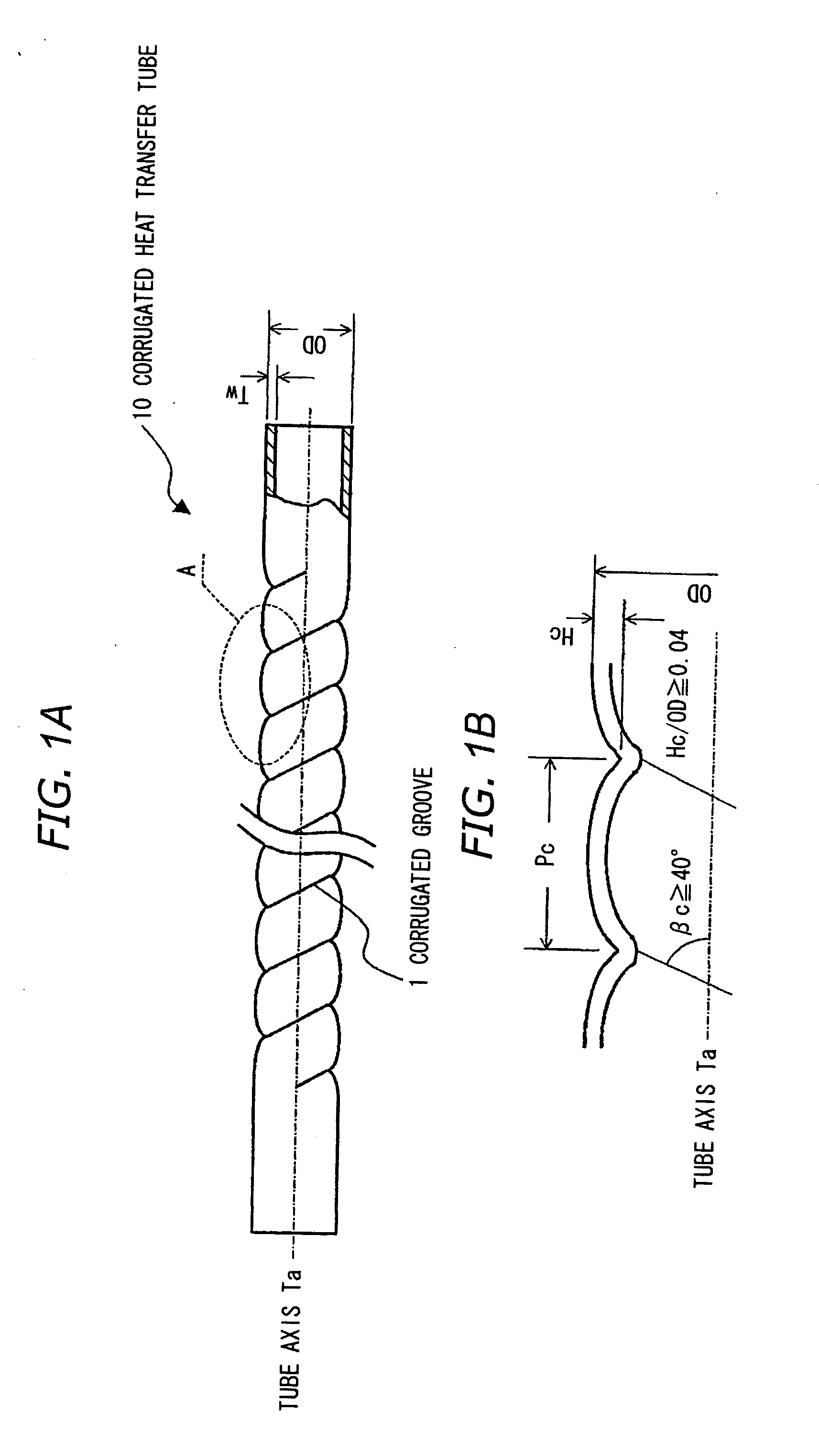
[0042]FIG. 1A is an explanatory diagram of an entire view showing structure of a heat transfer tube in a first preferred embodiment according to the present invention, and FIG. 1B is an enlarged cross-sectional view in region A of FIG. 1A.

[0043]A heat transfer tube (a corrugated heat transfer tube) 10 in this embodiment is formed of a one-thread corrugated tube (“one-thread” means that a number of a corrugated groove is one), and is used as a water tube that constitutes a heat exchanger (e.g., a water-refrigerant heat exchanger for a heat pump water heater), where a heat is exchanged between a water flowing inside the heat transfer tube 10 and a refrigerant flowing outside the heat transfer tube 10. The corrugated tube generally refers to a tube with an undulating helical structure in its inner / outer surface.

[0044]Let the corrugated groove depth and corrugation outside diameter of the corrugated heat transfer tube 10 in this embodiment be Hc and OD respectively, Hc / OD, which represe...

second embodiment

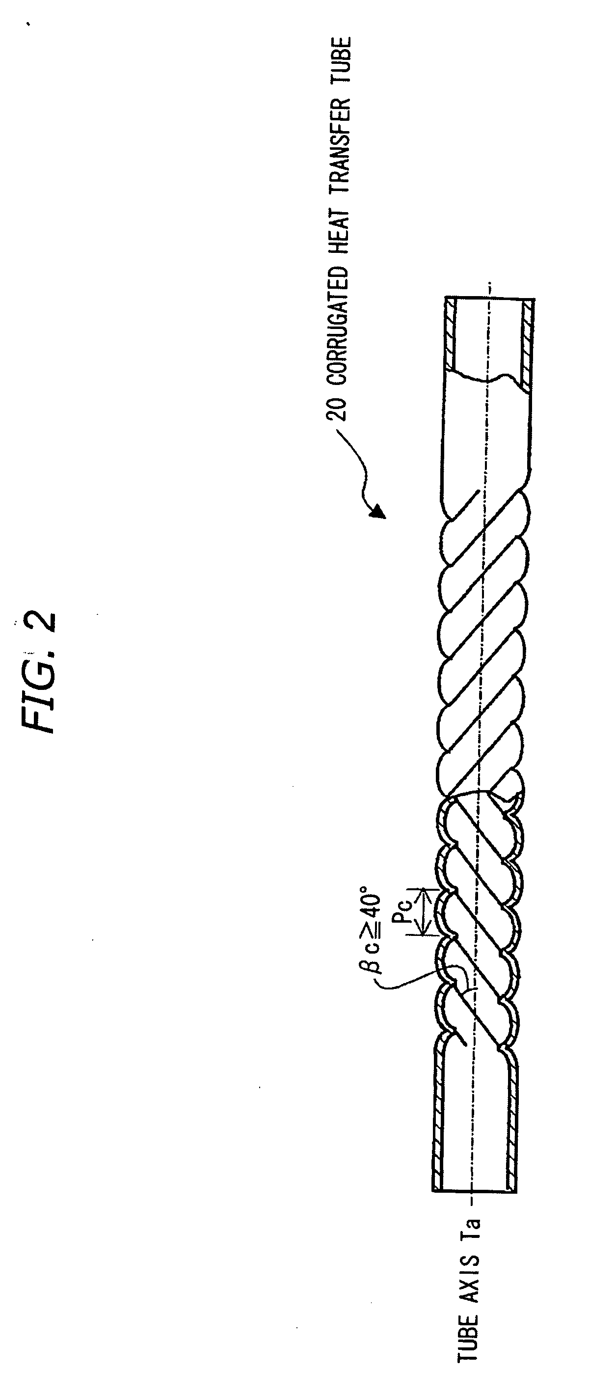
[0047]FIG. 2 is an explanatory diagram showing structure of a heat transfer tube in a second preferred embodiment according to the present invention.

[0048]While the heat transfer tube 10 in the first embodiment is formed from the one-thread corrugated tube, a heat transfer tube 20 in this second embodiment is formed from a three-thread corrugated tube (“three-thread” means that a number of a corrugated groove is three), and is used as a water tube that constitutes a heat exchanger. The more the number of threads, the higher the fabrication rate, which therefore results in a large cost merit.

[0049]Although the twist angle βc in three thread fabrication tends to be smaller than that of one thread fabrication, by reducing the spacing between the adjacent corrugated grooves 1, i.e., corrugation pitch Pc, a twist angle of 40° or higher, which is difficult to fabricate in the inner-grooved tube, can be realized.

[0050]Next, there is explained a heat exchanger equipped with the above corrug...

third embodiment

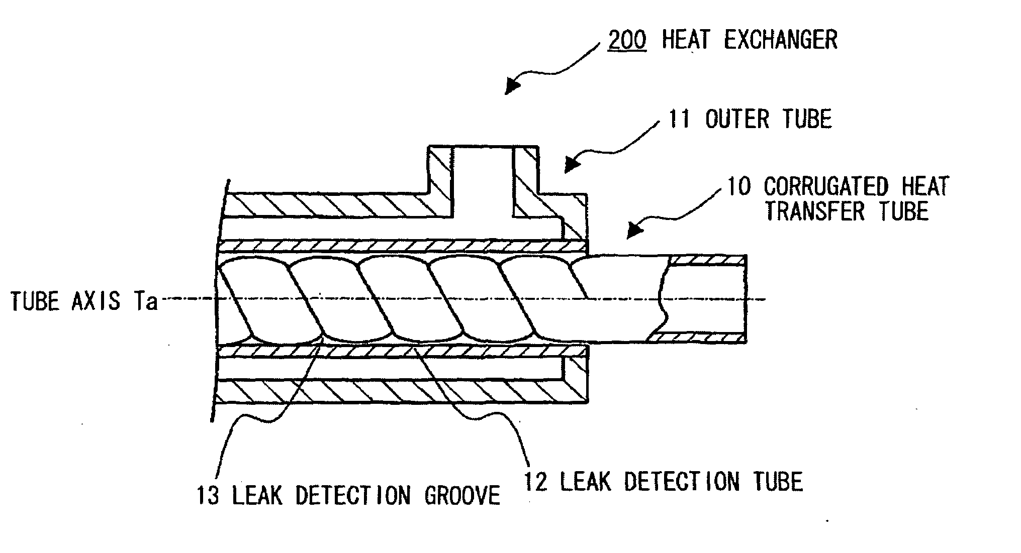
[0051]FIG. 3 is an explanatory diagram showing structure of a heat exchanger in a third preferred embodiment according to the present invention.

[0052]A heat exchanger (a double tube heat exchanger) 100 in this embodiment includes an outer tube 11 provided outside of the heat transfer tube (e.g., corrugated heat transfer tube 10) in the above-described embodiments that is used as an inner tube, where the heat exchanger is formed so that a refrigerant flows through an annular path between the corrugated heat transfer tube 10 and the outer tube 11.


PUM


Abstract

A heat transfer tube is formed with a corrugated water tube to be used in a heat exchanger, and satisfying 0.04≦Hc/OD, where Hc is the corrugated groove depth of the corrugated tube and OD is the corrugation outside diameter thereof.

Description

[0001]The present application is based on Japanese patent application No. 2006-038531, the entire contents of which are incorporated herein by reference.BACKGROUND OF THE INVENTION[0002]1. Field of the Invention[0003]The present invention relates to a heat transfer tube and a heat exchanger using the heat transfer tube, and particularly, to a heat transfer tube for a water-refrigerant heat exchanger used in a natural refrigerant heat pump water heater (which may herein be referred to as simply “heat pump water heater”), and a heat exchanger using the heat transfer tube.[0004]2. Description of the Related Art[0005]Conventionally well-known heat pump water heaters using a natural refrigerant (e.g., carbon dioxide refrigerant) employ generally two kinds of heat exchangers, i.e., a heat radiator and a heat absorber. The two heat exchangers use, as a heat transfer tube, refrigerant tubes for the heat radiator and for the heat absorber, respectively.[0006]In the heat pump water heaters, t...

Claims


Application Information

Patent Timeline
IPC IPC(8): F28F11/00
CPCF28D7/106F28F1/003F28F1/426F28F1/42F28F1/08
Inventor HORIGUCHI, KENKIKUCHI, KENICHIKOBAYASHI, RYUICHIHOFUKU, MAMORUKODAMA, KENJINOMURA, KATSUMI
Owner HITACHI CABLE
Why Eureka
Try Eureka