Phase Control Dimming Compatible Lighting Systems

a phase control and lighting system technology, applied in the field of electronic devices, can solve the problems of phase modulated signal, incompatible ballasts of many discharge lamps, phase modulated signal, etc., and achieve the effect of reducing the cost of phase control dimmers

Inactive Publication Date: 2011-03-31
SIGNIFY HLDG BV
View PDF99 Cites 61 Cited by
  • Summary
  • Abstract
  • Description
  • Claims
  • Application Information

AI Technical Summary

Benefits of technology

[0016]In a further embodiment of the present invention, a power control / lighting system includes a switching power converter having at least one input to receive a phase control dimming signal. The power control / lighting system also includes a controller having an input to receive the phase control dimming signal. The controller is configured to: (i) convert the phase control dimming signal into dimming information and (ii) generate a power factor correction (PFC) control signal for a switching power converter. The controller further includes a first output to provide the dimming information and a second output coupled to the switching power converter to provide the PFC control signal. The power control / lighting system also includes a lamp ballast coupled to the switching power converter and the second output of the controller and further includes a discharge-type lamp coupled to the lamp ballast.

Problems solved by technology

However, conventional phase control dimmers, such as a triac-based dimmer, that are designed for use with resistive loads, such as incandescent light bulbs, often do not perform well when supplying a raw, phase modulated signal to a reactive load, such as a switching power converter.
Ballasts for many discharge lamps are not compatible with phase control dimmers.
Phase control dimmers are ubiquitous but do not work well with reactive loads, such as lamp ballast 104.
Replacing or bypassing phase controlled dimmer adds additional cost to the installation of dimmer 102.
Additionally, lamp ballast 104 does not provide a full-range of dimming for lamp 106.

Method used


Image

  • Phase Control Dimming Compatible Lighting Systems
  • Phase Control Dimming Compatible Lighting Systems
  • Phase Control Dimming Compatible Lighting Systems

Examples


Embodiment Construction

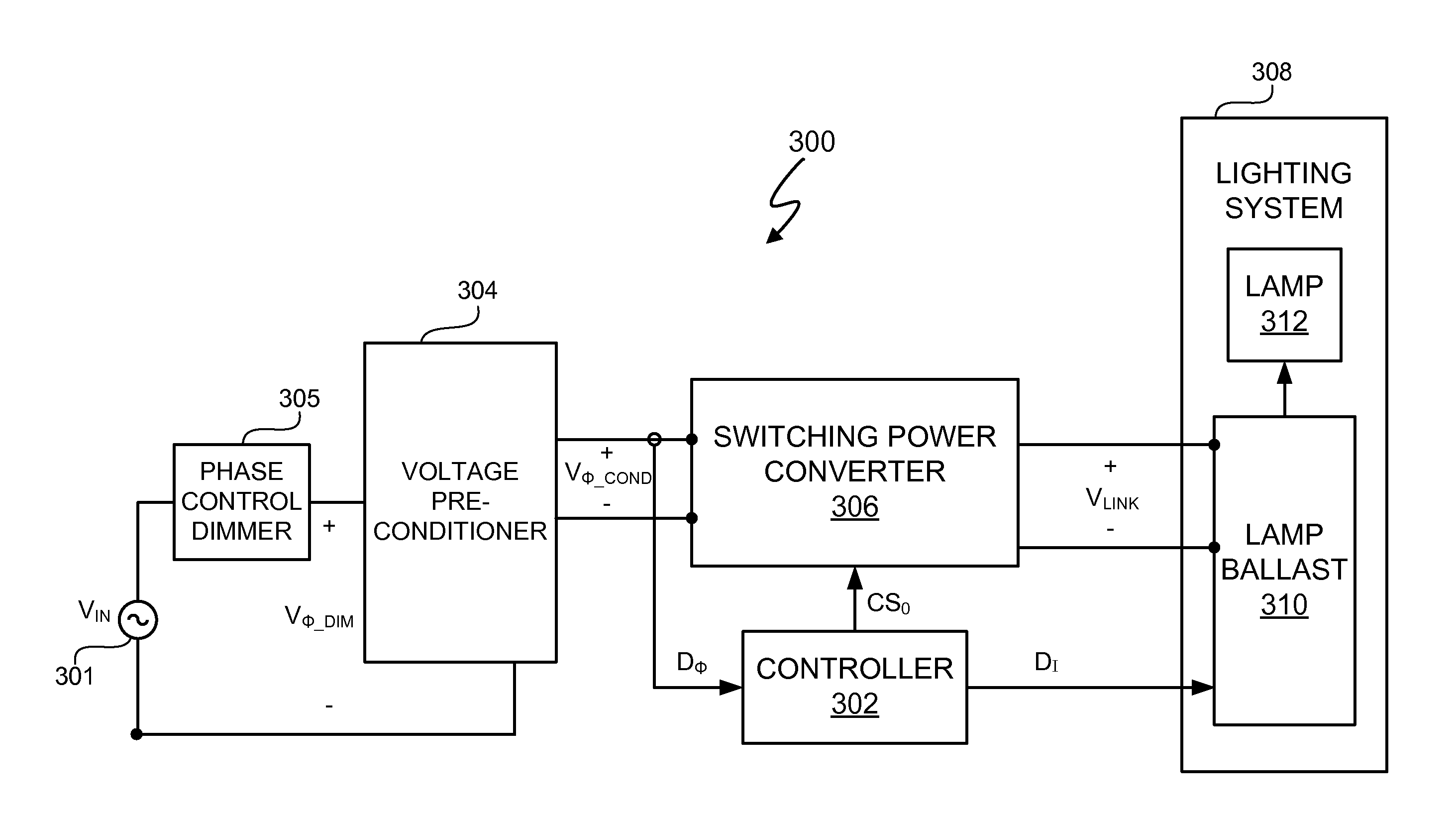
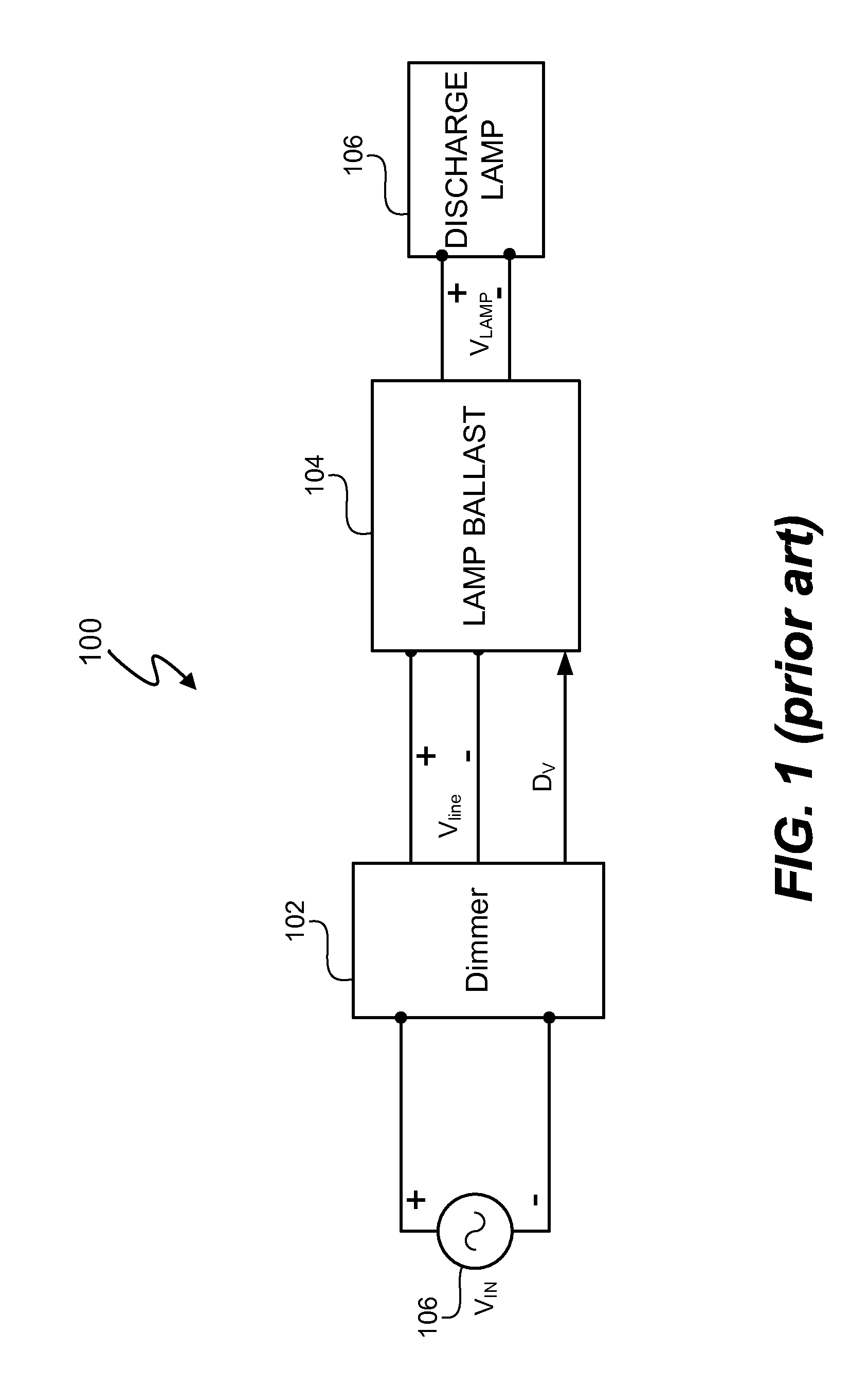
[0027]A power control / lighting system includes a controller to provide compatibility between a lamp ballast configured to receive a dedicated dimmer signal and a phase control dimmer. In at least one embodiment, the controller converts a phase control dimming signal into dimming information useable by a lamp ballast of a gas discharge lamp based lighting system. Additionally, in at least one embodiment, the controller also controls power factor correction of the power control / lighting system. In at least one embodiment, the controller provides dimming information based on the phase control dimming signal that allows the lamp ballast to be used in conjunction with a phase control dimmer. In at least one embodiment, the controller also enables a switching power converter to provide a sufficiently high resistive load during phase delays of the phase control dimmer to, for example, prevent ripple and missed chopping of a phase dimmer output signal. In at least one embodiment, the contro...


PUM


Abstract

A power control / lighting system includes a controller to provide compatibility between a lamp ballast configured to receive a dedicated dimmer signal and a phase control dimmer. In at least one embodiment, the controller converts a phase control dimming signal into dimming information useable by a lamp ballast of a gas discharge lamp based lighting system. Additionally, in at least one embodiment, the controller also controls power factor correction of the power control / lighting system. In at least one embodiment, the controller provides dimming information based on the phase control dimming signal that allows the lamp ballast to be used in conjunction with a phase control dimmer.

Description

CROSS REFERENCE TO RELATED APPLICATIONS[0001]U.S. patent application Ser. No. 11 / 967,269, entitled “Power Control System Using a Nonlinear Delta-Sigma Modulator with Nonlinear Power Conversion Process Modeling,” inventor John L. Melanson, Attorney Docket No. 1745-CA, and filed on Dec. 31, 2007 describes exemplary methods and systems and is incorporated by reference in its entirety. Referred to herein as Melanson I.[0002]U.S. patent application Ser. No. 11 / 967,271, entitled “Power Factor Correction Controller with Feedback Reduction,” inventor John L. Melanson, Attorney Docket No. 1756-CA, and filed on Dec. 31, 2007 describes exemplary methods and systems and is incorporated by reference in its entirety. Referred to herein as Melanson II.[0003]U.S. patent application Ser. No. 11 / 967,273, entitled “System and Method with Inductor Flyback Detection Using Switch Date Charge Characteristic Detection,” inventor John L. Melanson, Attorney Docket No. 1758-CA, and filed on Dec. 31, 2007 desc...

Claims


Application Information

Patent Timeline
Patent Type & Authority Applications(United States)
IPC IPC(8): H05B41/36
CPCH05B41/3924
Inventor DRAPER, WILLIAM A.GRISAMORE, ROBERT
Owner SIGNIFY HLDG BV
Why Eureka
Try Eureka