

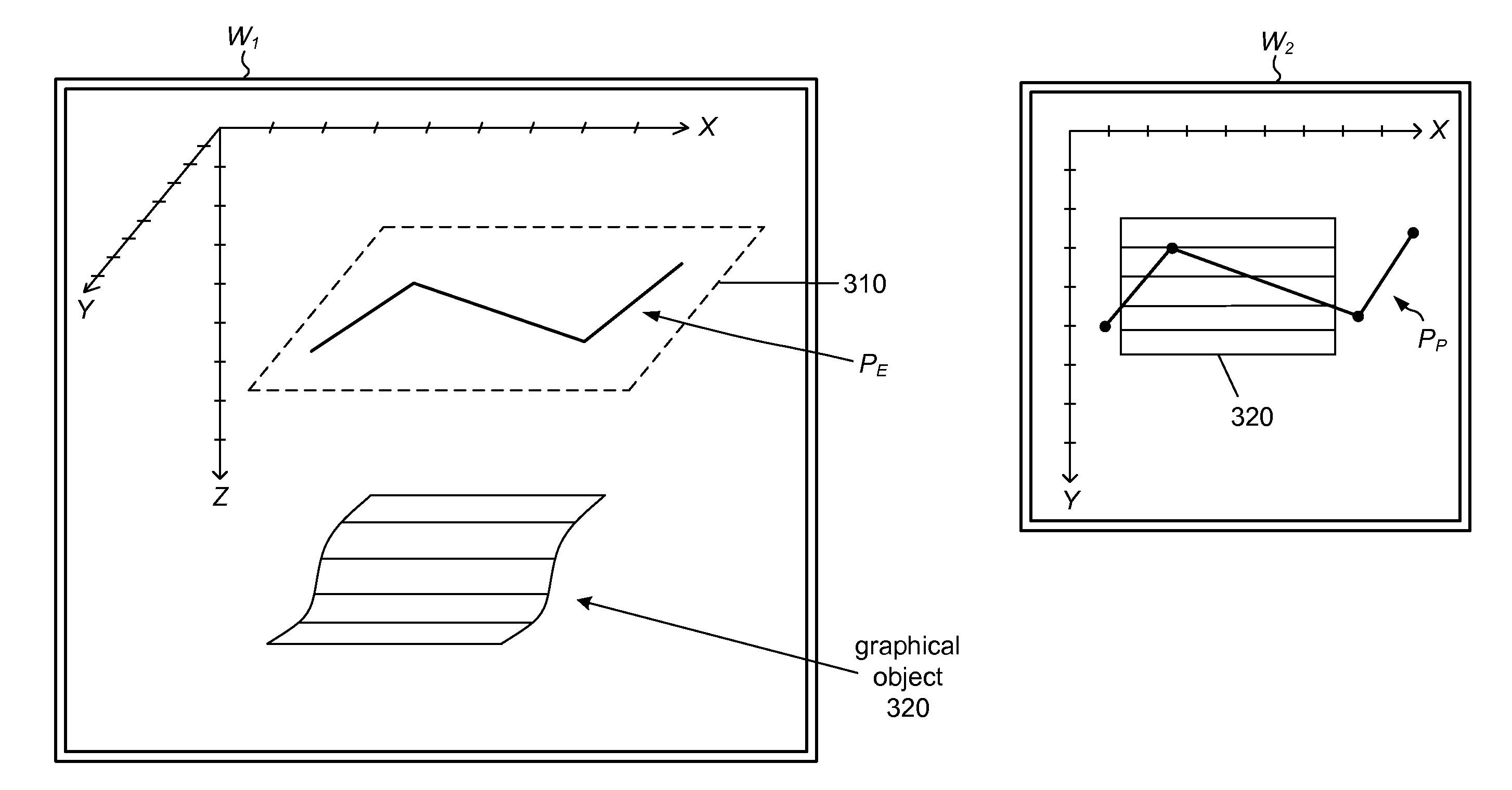
Drawing graphical objects in a 3D subsurface environment
a technology of drawing objects and subsurface environment, applied in the field of computer graphics, can solve problems such as difficulty in using tools
- Summary
- Abstract
- Description
- Claims
- Application Information
AI Technical Summary
Benefits of technology
Problems solved by technology
Method used
Image

Examples
Embodiment Construction
[0049]Incorporation by Reference: U.S. patent application Ser. No. 12 / 397,416 titled “Three-Dimensional Visualization of Images in the Earth's Subsurface”, filed on Mar. 4, 2009, invented by Donald Murray and Stuart Smith, is hereby incorporated by reference in its entirety as though fully and completely set forth herein.
[0050]Embodiments of the present invention may be realized in any of various forms. For example, in some embodiments, the present invention may be realized as a computer-implemented method, a computer-accessible memory medium, or a computer system. In other embodiments, the present invention may be realized using one or more custom-designed hardware devices such as ASICs or FPGA's.
[0051]A memory medium is a medium configured for the storage and retrieval of information. Examples of memory media include: various kinds of semiconductor memory such as RAM and ROM; various kinds of magnetic media such as magnetic disk, tape, strip and film; various kinds of optical medi...
PUM
 Abstract
Description
Claims
Application Information