Touch pad module assembly structure

a technology of touch pad and assembly structure, which is applied in the direction of instruments, portable computer details, electrical apparatus casings/cabinets/drawers, etc., can solve the problems of low production output and high labor intensity in assembly, and achieve the effect of improving the assembly structure of the touch pad modul

Active Publication Date: 2011-03-31
QUANTA COMPUTER INC
View PDF28 Cites 22 Cited by
  • Summary
  • Abstract
  • Description
  • Claims
  • Application Information

AI Technical Summary

Benefits of technology

It is therefore an objective of the present invention to

Problems solved by technology

Such assembling way would need lots of

Method used


Image

  • Touch pad module assembly structure
  • Touch pad module assembly structure
  • Touch pad module assembly structure

Examples


Embodiment Construction

Reference will now be made in detail to the present preferred embodiments of the invention, examples of which are illustrated in the accompanying drawings. Wherever possible, the same reference numbers are used in the drawings and the description to refer to the same or like parts.

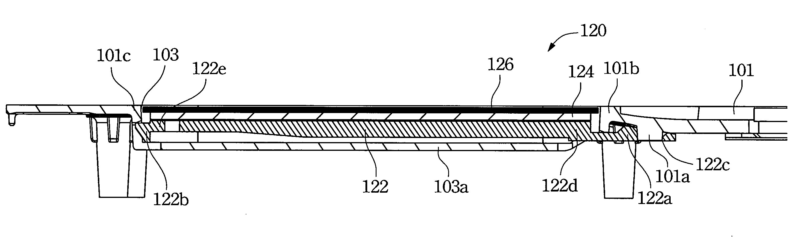
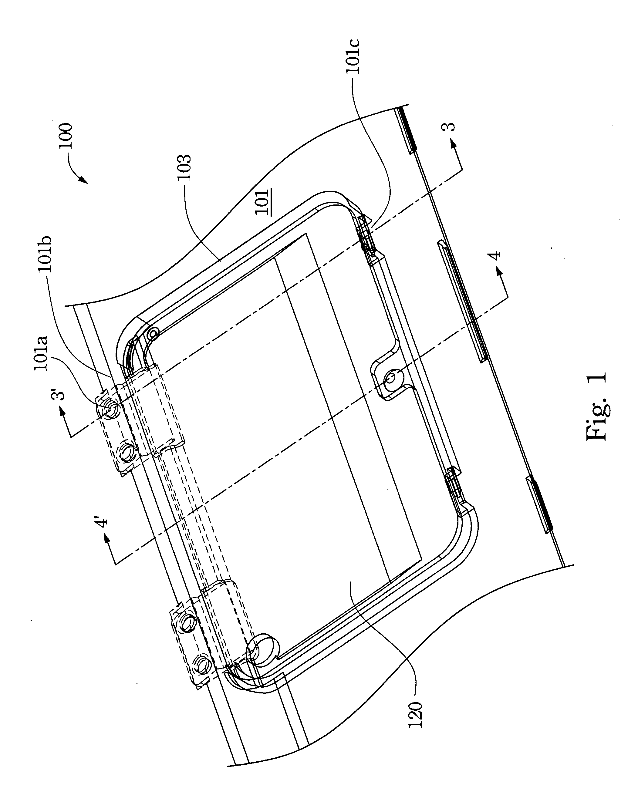
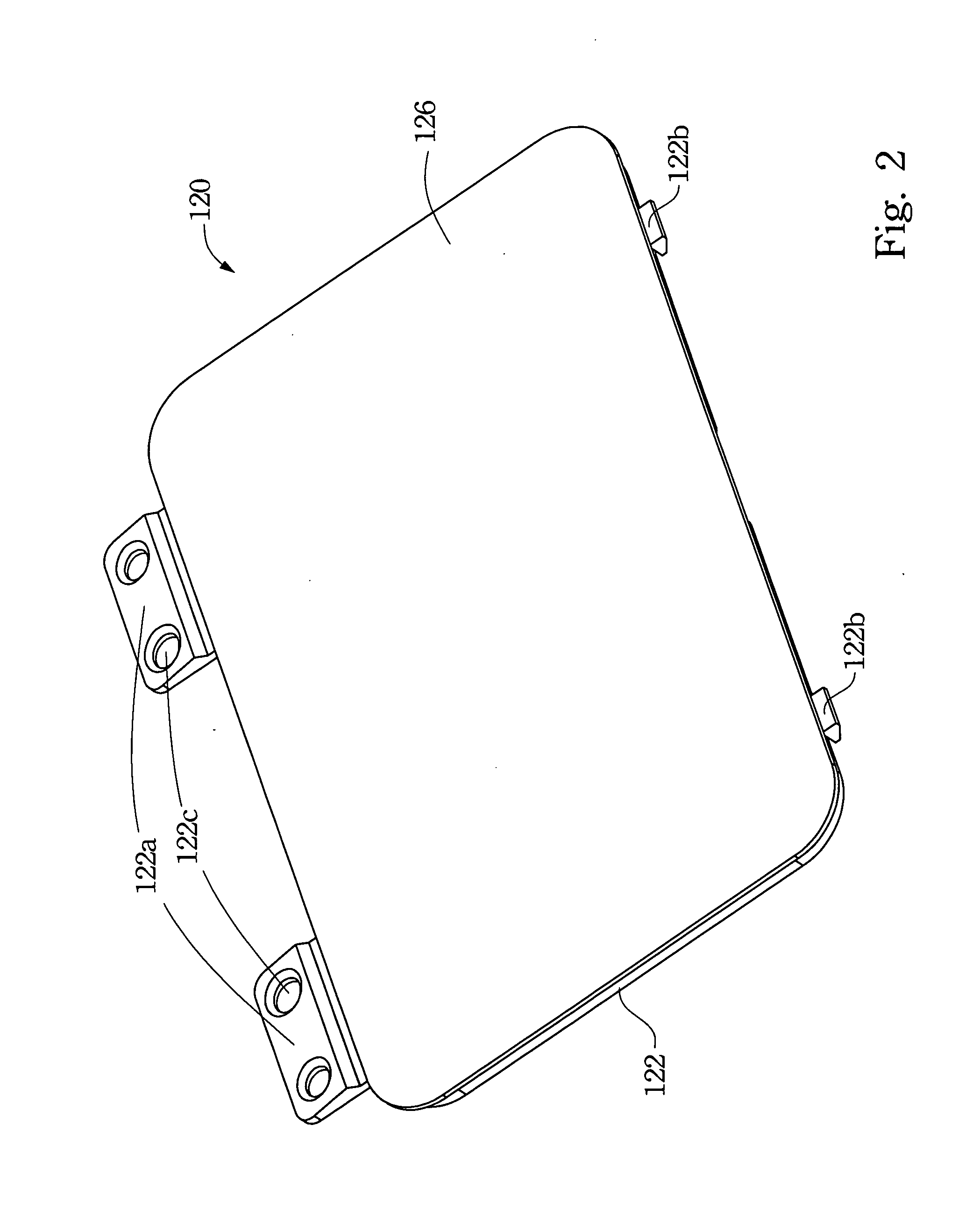
FIG. 1 illustrates a touch pad module assembly structure according to one embodiment of this invention. FIG. 2 illustrates the touch pad module in FIG. 1. A touch pad module 120 is assembled within a concave area 103 of a housing 101 of a computer device 100 (such as a notebook computer). The touch pad module 120 provides a cursor control function, i.e. same function as a computer does. The embodiment herein discloses a screw-less assembly method, thereby reducing labor efforts and accelerating assembly speed. The touch pad module assembly structure and assembly method is described as below.

FIG. 3 illustrates a cross-sectional view taken along 3-3′ in FIG. 1. The cross-section line 3-3′ goes across the tou...


PUM


Abstract

A touch pad module assembly structure includes a housing and a touch module. The housing includes a generally rectangular concave area, which includes a bottom surface, two housing edges, a step, a position pin and a convex member. The step is disposed closer to one of the two housing edges than the other thereof. The position pin is disposed on an inner surface of the one of the two housing edges. The convex member is disposed closer to the other of the two housing edges. The touch module includes a support member, which includes a position member and a hook member. The position member is disposed at an edge of the support member and includes a position hole to be engaged with the position pin. The hook member is disposed at an opposite edge of the support member and coupled with the other of the two housing edges.

Description

RELATED APPLICATIONSThis application claims priority to Taiwan Application Serial Number 98218076, filed Sep. 30, 2009, which is herein incorporated by reference.BACKGROUND1. Field of InventionThe present invention relates to a touch pad module. More particularly, the present invention relates to a touch pad module of a computer device.2. Description of Related ArtA touch pad module is one of the essential parts of each notebook computer in order to perform a computer mouse's function within an operation system. A conventional touch pad module is assembled a computer housing by using nuts and bolts. Such assembling way would need lots of labor efforts and low production output. For the forgoing reasons, there is a need for improving the touch pad module assembly structure.SUMMARYIt is therefore an objective of the present invention to provide an improved touch pad module assembly structure.In accordance with the foregoing and other objectives of the present invention, a touch pad mo...

Claims


Application Information

Patent Timeline
IPC IPC(8): G06F1/16
CPCG06F1/169
Inventor CHIANG, TSUNG-JULIN, HSIU-PEN
Owner QUANTA COMPUTER INC
Why Eureka
Try Eureka