Packet transmission device and packet transmission method

a packet transmission and packet technology, applied in the field of packet transmission apparatus and packet transmission method, can solve problems such as processing delay, and achieve the effect of preventing deterioration of communication quality and preventing increase of delay tim

Inactive Publication Date: 2011-03-31
PANASONIC CORP
View PDF9 Cites 8 Cited by
  • Summary
  • Abstract
  • Description
  • Claims
  • Application Information

AI Technical Summary

Benefits of technology

[0031]According to the present invention, when a transmission channel conditions is judged to be poor, low QoS packets are preferentially included in transmission frame components, and, on the other hand, when a transmission channel condition is judged to be good, high QoS packets are preferentially included in transmission frame components. By this means, it is possible to prevent increase in delay time until high QoS packets arrive and prevent deterioration of communication quality due to radio errors, and also realize a packet transmitting apparatus to keep the transmission rate of low QoS packets.

Problems solved by technology

In addition, there are a transmission delay (see FIG. 2j.) to transmit radio frames containing NACK information from the reception source transmitter transmits to transmission source transmitter, and a processing delay in the transmission source (see FIG. 2k.) in order that the transmission source receiver receives radio frames, performs demodulation and decoding processing, detects NACK information and reports the detection result to the transmission source transmitter.

Method used


Image

  • Packet transmission device and packet transmission method
  • Packet transmission device and packet transmission method
  • Packet transmission device and packet transmission method

Examples


embodiment 1

[0045]FIG. 3 is a block diagram showing a configuration of a packet transmitting apparatus according to Embodiment 1 of the present invention. The present embodiment is an example of a case in which the packet transmitting apparatus is a digital mobile communication apparatus.

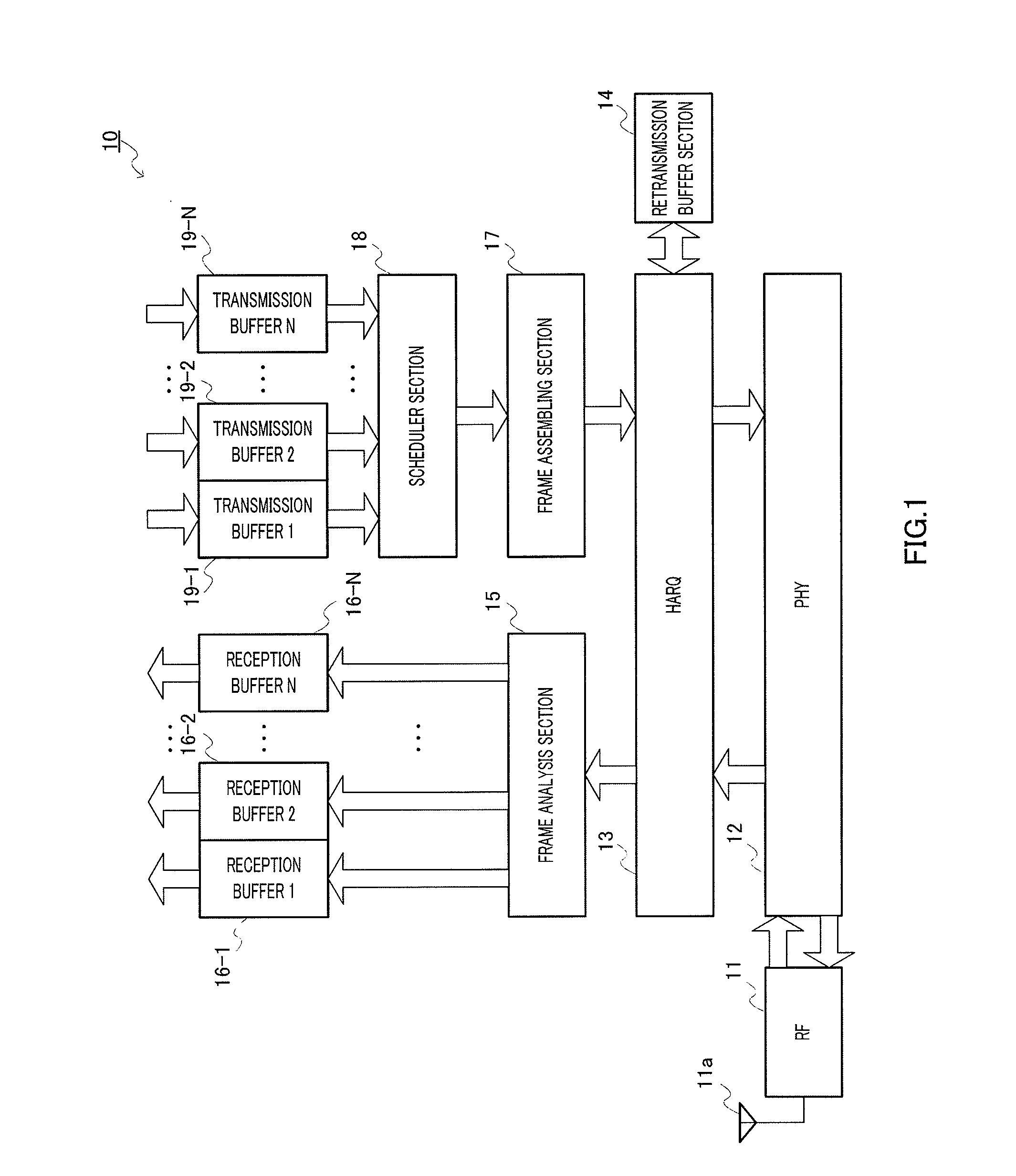
[0046]In FIG. 3, packet transmitting apparatus 100 is configured to include RF processing section 101, baseband processing section 102 (abbreviated as “PHY” in FIG. 3), retransmission control section 103 (abbreviated as “HARQ” in FIG. 3), retransmission buffer section 104, frame analysis section 105, reception buffer sections 106-1 to 106-N, frame assembling section 107, adaptive scheduler section 108, transmission buffer sections 109-1 to 109-N and transmission channel judgment section 110.

[0047]RF processing section 101 converts a digital signal radio frame to an analog signal radio frame, and sends the result from radio antenna 101a by radio. In addition, RF processing section 101 converts an analog signal r...

embodiment 2

[0114]FIG. 11 is a block diagram showing a configuration of a packet transmitting apparatus according to Embodiment 2 of the present invention. The same components as in FIG. 3 are assigned the same reference numerals and overlapping descriptions will be omitted.

[0115]In FIG. 11, packet transmitting apparatus 800 is configured to include RF processing section 101, baseband processing section 102, retransmission control section 803, retransmission buffer section 104, frame analysis section 105, reception buffer sections 106-1 to 106-N, frame assembling section 107, adaptive scheduler section 808, transmission buffer sections 109-1 to 109-N, transmission channel judgment section 810 and multiple transmission buffers 811.

[0116]RF processing section 101 converts a digital signal radio frame to an analog signal radio frame and sends the result from radio antenna 101a by radio, and converts an analog signal radio frame by radio to a digital signal radio frame. By this means, baseband proc...


PUM


Abstract

Provided are a packet transmission device and a packet transmission method which can effectively use a radio band while suppressing a processing overhead. A packet transmission device (100) includes: a transmission path judgment unit (110) which judges a transmission path state according to a radio channel quality estimation result; and an adaptive scheduler unit (108) which includes a low QoS packet into a transmission frame constituent element with a higher priority if the transmission path state is judged to be bad and a high QoS packet into the transmission frame constituent element with a higher priority if the transmission path state is judged to be good. That is, the adaptive scheduler unit (108) allocates a low QoS packet with a higher priority when it is judged that the possibility of generation of a radio error is high and the transmission path state is bad.

Description

TECHNICAL FIELD[0001]The present invention relates to a packet transmitting apparatus and a packet transmitting method for digital mobile communication to allow packet communication.BACKGROUND ART[0002]Conventionally, in the field of radio communication systems, a communication scheme referred to as “HSDPA” has been standardized whereby a plurality of communication terminal apparatuses share high speed and large capacity downlink channels to perform high-speed packet transmission in the downlink, besides communication schemes that performs transmission to communication terminal apparatuses using DPCHs (dedicated physical channels).[0003]In radio communication, propagation conditions are significantly unstable, and the capacity of communication channels widely changes over time. HSDPA (High Speed Downlink Packet Access) uses this. HSDPA is a technique of performing high-speed transmission using M-ary modulation and low coding rate when communication conditions are good, in order to i...

Claims


Application Information

Patent Timeline
Patent Type & Authority Applications(United States)
IPC IPC(8): H04L12/56H04L47/6275H04W28/04H04W28/18H04W72/04H04W72/08H04W88/02
CPCH04L1/1825H04W72/1236H04W72/1231H04L1/1887H04W72/543H04W72/542
Inventor YUI, TOMOHIRO
Owner PANASONIC CORP
Why Eureka
Try Eureka