Fixing apparatus and image forming apparatus

Inactive Publication Date: 2011-03-31
SHARP KK
View PDF5 Cites 4 Cited by
  • Summary
  • Abstract
  • Description
  • Claims
  • Application Information

AI Technical Summary

Benefits of technology

[0052]In this aspect, the regulation belt is wound around at least the heat roller (generally, the heat roller whose surface has a friction coefficient smaller than the friction coefficient of the surface of the fixing roller), and thereby damage to the edge portion (in particular, the edge face) of the fixing belt can be suppressed while reliably regulating wobbling and deviation of the fixing belt on the heat roller, on which the fixing belt tends to easily move

Problems solved by technology

Meanwhile, along with accelerated operation of an image forming apparatus, if the process speed becomes faster, the movement speed (fixing speed) of a recording sheet that passes through the fixing nip portion in a fixing apparatus also becomes faster, and thus there are cases in which sufficient heat cannot be given to an unfixed toner image of the recording sheet in the fixing nip portion, so that fixing processing cannot be performed appropriately.
With the conventional configuration in which an elastic roller serving as a fixing roller is provided with a heat source such as a halogen heater, there is the problem that the thermal conductivity of the elastic layer of the fixing roller is very low, and thus the surface temperature of the elastic layer tends not to follow the temperature change of the heat source.
For this reason, if the elastic layer is thickened as in the case of the above (1), not only does the problem of the temperature following capability of the surface of the fixing roller become more noticeable, but also the thermal conductivity of the elastic layer becomes still lower, which leads to the problem that the warm-up time for heating becomes longer by that extent, and the problem that powe

Method used


Image

  • Fixing apparatus and image forming apparatus
  • Fixing apparatus and image forming apparatus
  • Fixing apparatus and image forming apparatus

Examples


Example

First Embodiment

[0118]FIGS. 4, 5A, and 5B are schematic diagrams showing a state where regulation belts 38 are provided in the fixing apparatus 12 shown in FIG. 3. FIGS. 4 and 5B show a lateral view thereof, and FIG. 5A shows a plan view thereof. Note that the pressure roller 32 is omitted in FIGS. 5A and 5B.

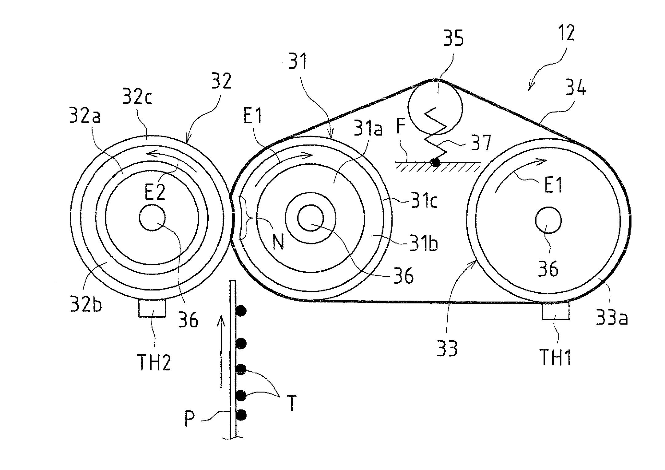
[0119]As shown in FIGS. 4, 5A, and 5B, the regulation belts 38 are wound around at least one (here, both sides) of both sides in the axial direction (the direction X in FIG. 5A) of at least one roller (33, 35) among the fixing roller 31, the heat roller 33, and the tension roller 35.

[0120]Specifically, the regulation belts 38 are wound around at least one roller (33, 35) among the fixing roller 31, the heat roller 33, and the tension roller 35, along at least a part (here, a first unwound area 341a) of unwound areas (here, first to third unwound areas 341a, 341b and 341c) where the fixing belt 34 is separated from the fixing roller 31, the heat roller 33, and the tension roller ...

Example

Second Embodiment

[0143]FIG. 9 is a lateral view illustrating a fixing apparatus 121 according to a second embodiment. Note that in the second embodiment shown in FIG. 9, the same reference numerals are given to the same constituent elements as those in the first embodiment, and a description thereof is omitted. The same applies to third to seventh embodiments described later.

[0144]In the second embodiment, regulation belts 381 and rollers 331 and 351 around which the regulation belts 381 are wound are engaged with each other using recessions and projections.

[0145]Specifically, the regulation belts 381 are obtained by providing the regulation belts 38 in the first embodiment with a plurality of projecting portions (for example, a plurality of projecting line portions in the axial direction X) 381a with equally-spaced intervals in the circumferential direction Y on the inner circumferential face. Other than this configuration, the regulation belts 381 are assumed to have the same conf...

Example

Third Embodiment

[0150]FIGS. 10A and 10B are cross-sectional views illustrating a fixing apparatus 122 according to the third embodiment. FIG. 10A shows a guide groove G provided in a heat roller 332, and FIG. 10B shows a guide groove G provided in a tension roller 352.

[0151]In the third embodiment, at least one of the rollers 332 and 352 (here, both the rollers) around which the regulation belts 38 are wound has the guide grooves G in which the regulation belts 38 are disposed formed over the whole circumference. Note that since the configuration of both sides of the heat roller 332 and the tension roller 352 is the same, FIGS. 10A and 10B show the configuration of one side, and the configuration of the other side is omitted in the figures. The same also applies to the fourth to seventh embodiments shown in FIGS. 11A to 14B described later.

[0152]Other than this configuration, the heat roller 332 and the tension roller 352 are assumed to have the same configuration as that of the hea...


PUM


Abstract

In one embodiment, in a fixing apparatus that is provided with a plurality of rollers including a fixing roller, and an endless fixing belt that is wound around the plurality of rollers, a regulation belt for regulating movement of the fixing belt in the axial direction is wound around at least one of both sides in the axial direction of at least one roller (for example, two rollers) among the plurality of rollers.

Description

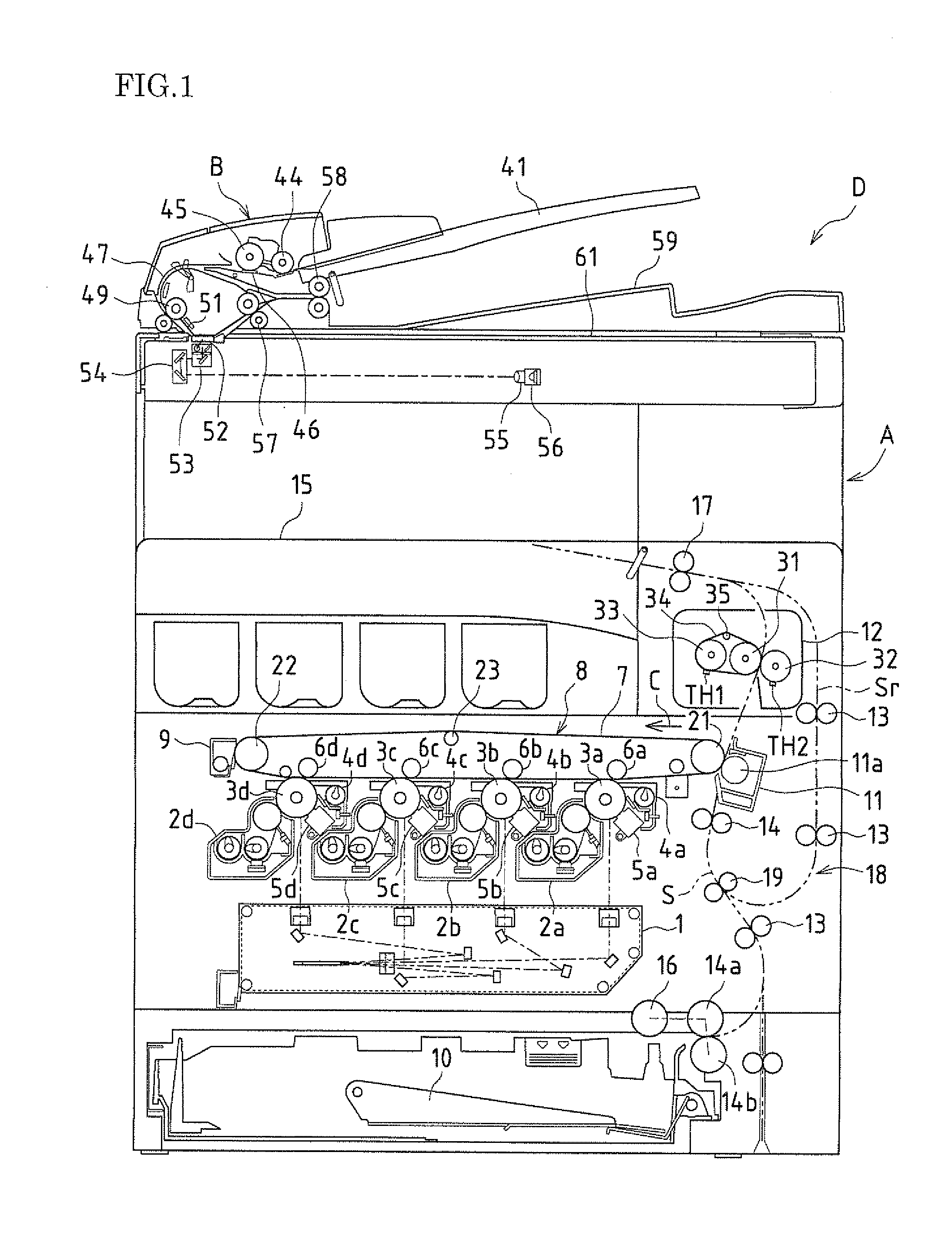
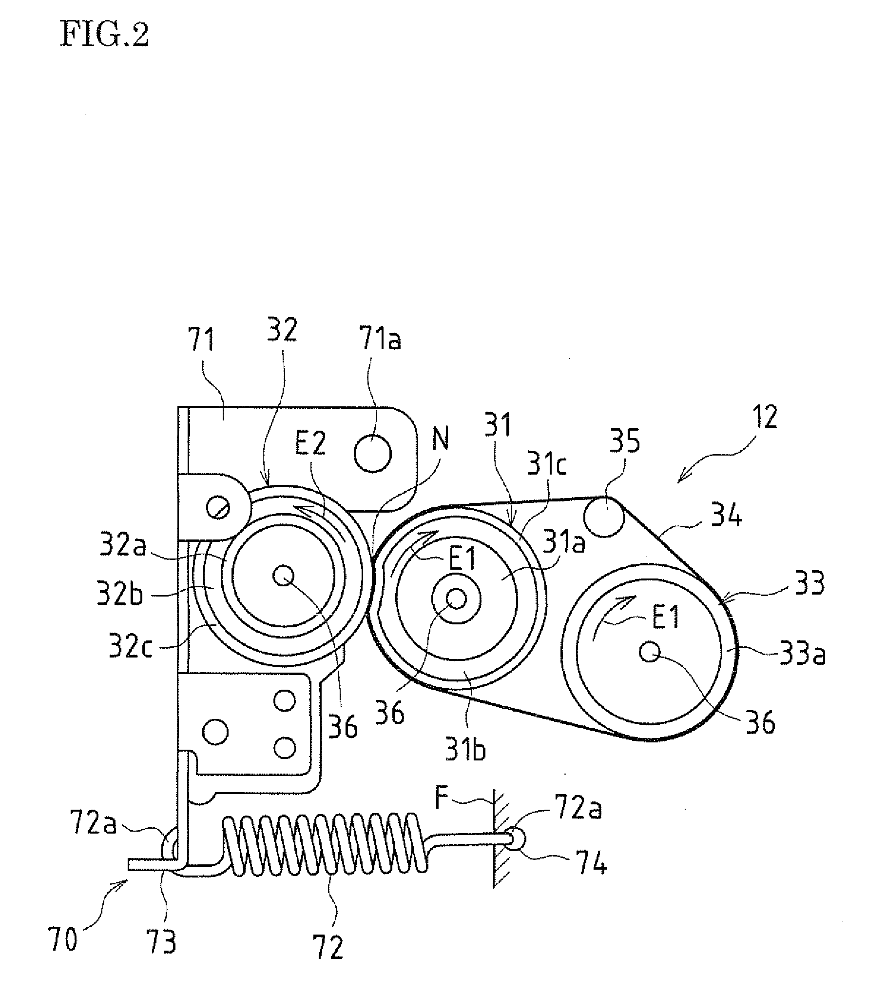
CROSS-REFERENCE TO RELATED APPLICATION[0001]This application claims priority under 35 U.S.C. §119(a) on Patent Application No. 2009-221195 filed in Japan on Sep. 25, 2009, the entire contents of which are herein incorporated by reference.BACKGROUND OF THE INVENTION[0002]1. Field of the Invention[0003]The present invention relates to a fixing apparatus, in particular a fixing apparatus that is applicable in an electrophotographic image forming apparatus such as a copying machine or a printer, and an image forming apparatus provided with the same.[0004]2. Related Art[0005]Fixing apparatuses that adopt a heat roller fixing method are widely used as fixing apparatuses of this type. Ordinarily, a fixing apparatus that adopts a heat roller fixing method is provided with a fixing roller and a pressure roller, which are a pair of rollers that are pressed against each other, and the pair of rollers is heated to a predetermined temperature (fixing temperature) using a heat source such as a ha...

Claims


Application Information

Patent Timeline
IPC IPC(8): G03G15/20
CPCG03G15/2064G03G2215/2032G03G2215/00168G03G2215/00143
Inventor AMEMIYA, MASAKIYAMANAKA, TAKASHIASAKAWA, MASAYANAKAMURA, HIROKAZUINOUE, NORIKO
Owner SHARP KK
Why Eureka
Try Eureka