
Pulse wave measurement device and pulse wave measuring

a measurement device and pulse wave technology, applied in the field of pulse wave measurement devices and pulse wave measuring apparatuses, can solve the problems of high inspection cost of mri and x-ray ct, unsuitable daily monitoring, and insufficient early detection support of medical systems, so as to reduce measurement variations and achieve high accuracy of pulse wave measuremen

Inactive Publication Date: 2011-03-31
MURATA MFG CO LTD
View PDF6 Cites 15 Cited by
  • Summary
  • Abstract
  • Description
  • Claims
  • Application Information

AI Technical Summary

Benefits of technology

The invention describes an improved way to measure pulses by reducing errors caused when applying pressure during measurements. This results in higher accuracy for detecting pulses.

Problems solved by technology

The technical problem addressed in this patent text is the need for an accurate and cost-effective method for early detection and preventive medicine for circulatory diseases caused by hardening of the arteries, which is currently not fully supported by the medical system. The current popular diagnostic equipment such as MRI and X-ray CT are expensive and not suitable for daily monitoring. The pulse wave velocity method is a simple and cost-effective technique but its accuracy is not satisfactory high. The patent text describes a tonometric pulse wave measuring apparatus that measures the intra-arterial pressure by flattening the artery and measuring the pressure using a sensor element, but this technique is insufficient for identifying individual differences and suffers from crosstalk.

Method used


Image

  • Pulse wave measurement device and pulse wave measuring
  • Pulse wave measurement device and pulse wave measuring
  • Pulse wave measurement device and pulse wave measuring

Examples


Embodiment Construction

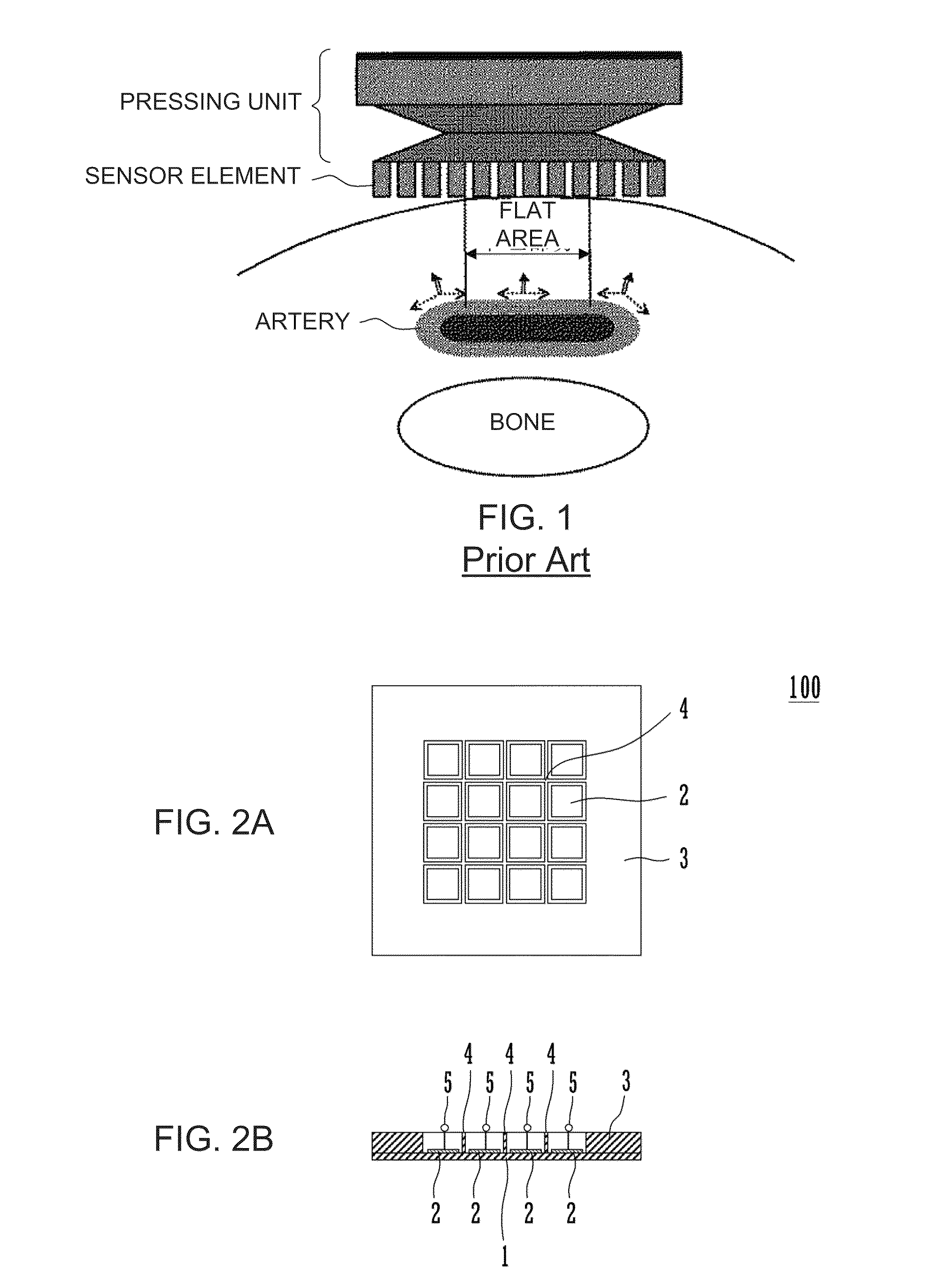
[0023]FIG. 2A is a plan view of a pulse wave measurement device 100 according to a first exemplary embodiment, and FIG. 2B is frontal view thereof.

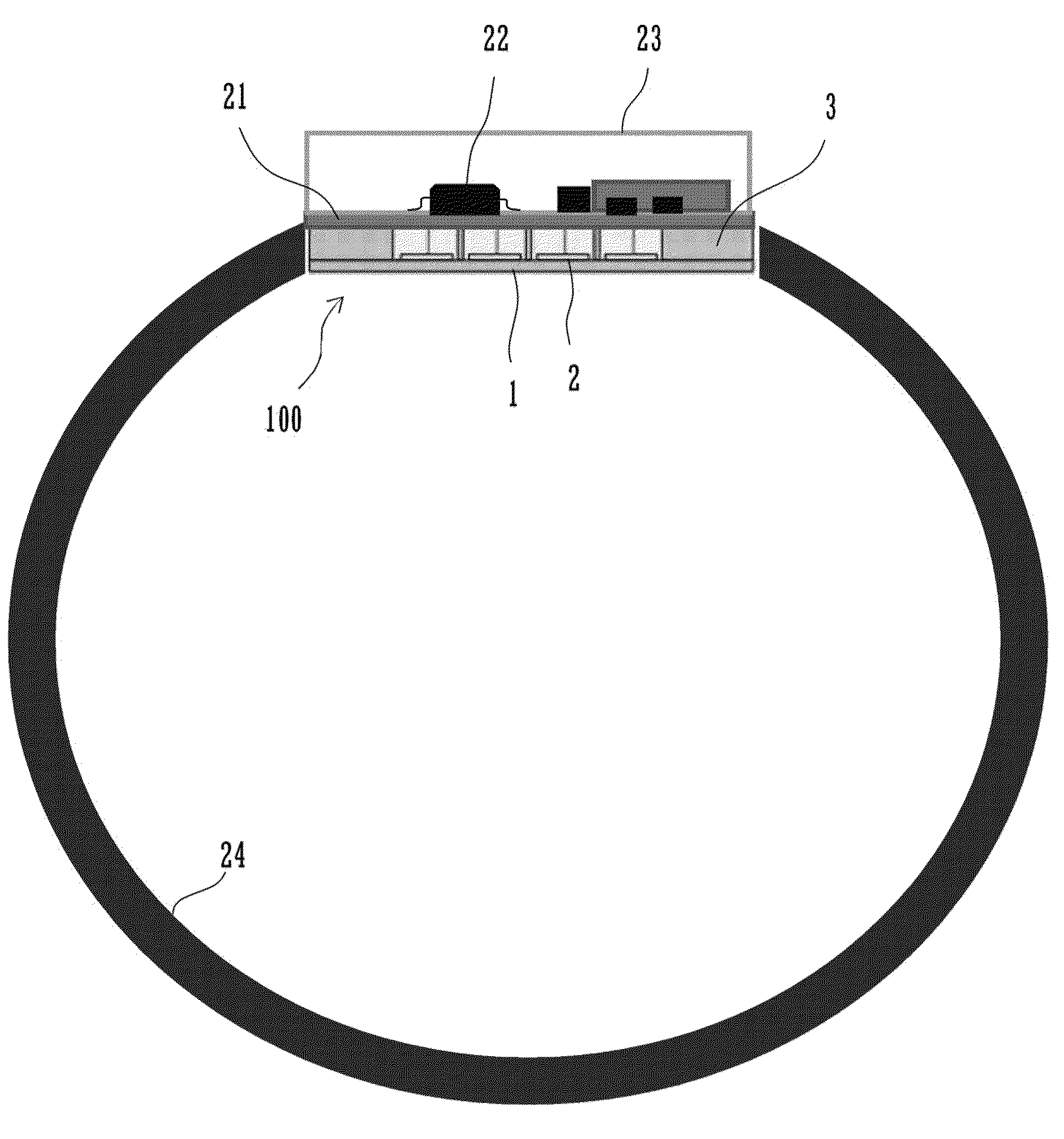
[0024]The pulse wave measurement device 100 illustrated in FIGS. 2A and 2B includes a vibrating membrane 1 configured to transfer displacement of a skin surface caused by a pulse wave, a frame portion 3 configured to fix the outer region of the vibrating membrane 1, a partitioning portion 4 configured to partition a central region of the vibrating membrane 1 into a plurality of sections, and a plurality of sensor elements 2 arranged on the vibrating membrane 1 within the plurality of sections and configured to convert vibration of the vibrating membrane 1 into an electric signal.

[0025]The partitioning portion 4 is coupled to the vibrating membrane 1. The vibrating membrane 1 is coupled to the frame portion 3. Thus, the sections of the vibrating membrane 1 partitioned by the partitioning portion 4 vibrate individually, and each section of ...


PUM


Abstract

A pulse wave measurement device includes a vibrating membrane configured to transfer displacement of a skin surface caused by a pulse wave, a frame portion configured to fix the outer region of the vibrating membrane, a partitioning portion configured to partition a central region of the vibrating membrane into a plurality of sections, and a plurality of sensor elements respectively provided in the plurality of sections and arranged on the vibrating membrane within each of the plurality of sections. The sensor element in each section is configured to convert vibration of the vibrating membrane in that section into an electric signal. The partitioning portion is coupled to the vibrating membrane. The vibrating membrane is coupled to the frame portion. Thus, the sections of the vibrating membrane partitioned by the partitioning portion vibrate individually, and each section of the vibrating membrane does not substantially interfere with the other sections.

Description


Claims


Application Information

Patent Timeline
Owner MURATA MFG CO LTD
Learn More