Foldable, implantable electrode assembly and tool for implanting same

a technology of electrodes and tools, applied in the field of electrode arrays, can solve problems such as increasing likelihood, and achieve the effect of modulating undesired pain signals and minimizing likelihood

Active Publication Date: 2011-03-31
STRYKER CORP
View PDF2 Cites 165 Cited by
  • Summary
  • Abstract
  • Description
  • Claims
  • Application Information

AI Technical Summary

Benefits of technology

[0021]Owing to the arrangement of the electrodes in the row by column array, the electrodes of this invention are disposed over an area that has both length and width. When the assembly is positioned over tissue, for example, the spinal cord dura, current pulses can be directed through the underlying tissue in a number of different paths. This increases the likelihood that current will flow through and therefore activate specific nerves in the dorsal column that will appreciably modulate undesired pain signals.
[0022]The curved shape of the frame means that the electrode assembly as a whole has a curved shape. The curved shaped of the electrode assembly causes the assembly to conform relatively closely to the tissue against which it is placed. This conformance minimizes the likelihood that the assembly will move from the implanted position.

Problems solved by technology

This increases the likelihood that current will flow through and therefore activate specific nerves in the dorsal column that will appreciably modulate undesired pain signals.

Method used


Image

  • Foldable, implantable electrode assembly and tool for implanting same
  • Foldable, implantable electrode assembly and tool for implanting same
  • Foldable, implantable electrode assembly and tool for implanting same

Examples


Embodiment Construction

I. Electrode Array Assembly

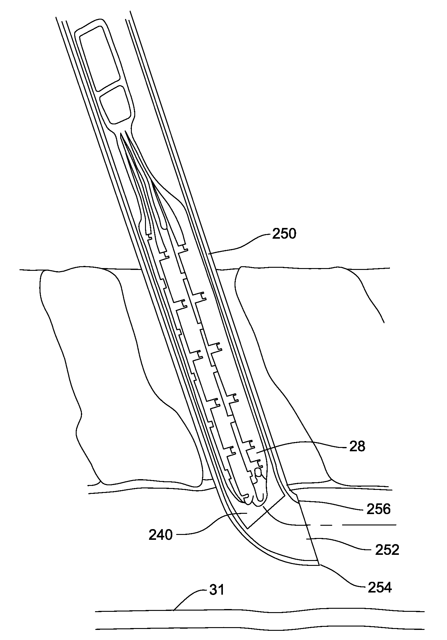
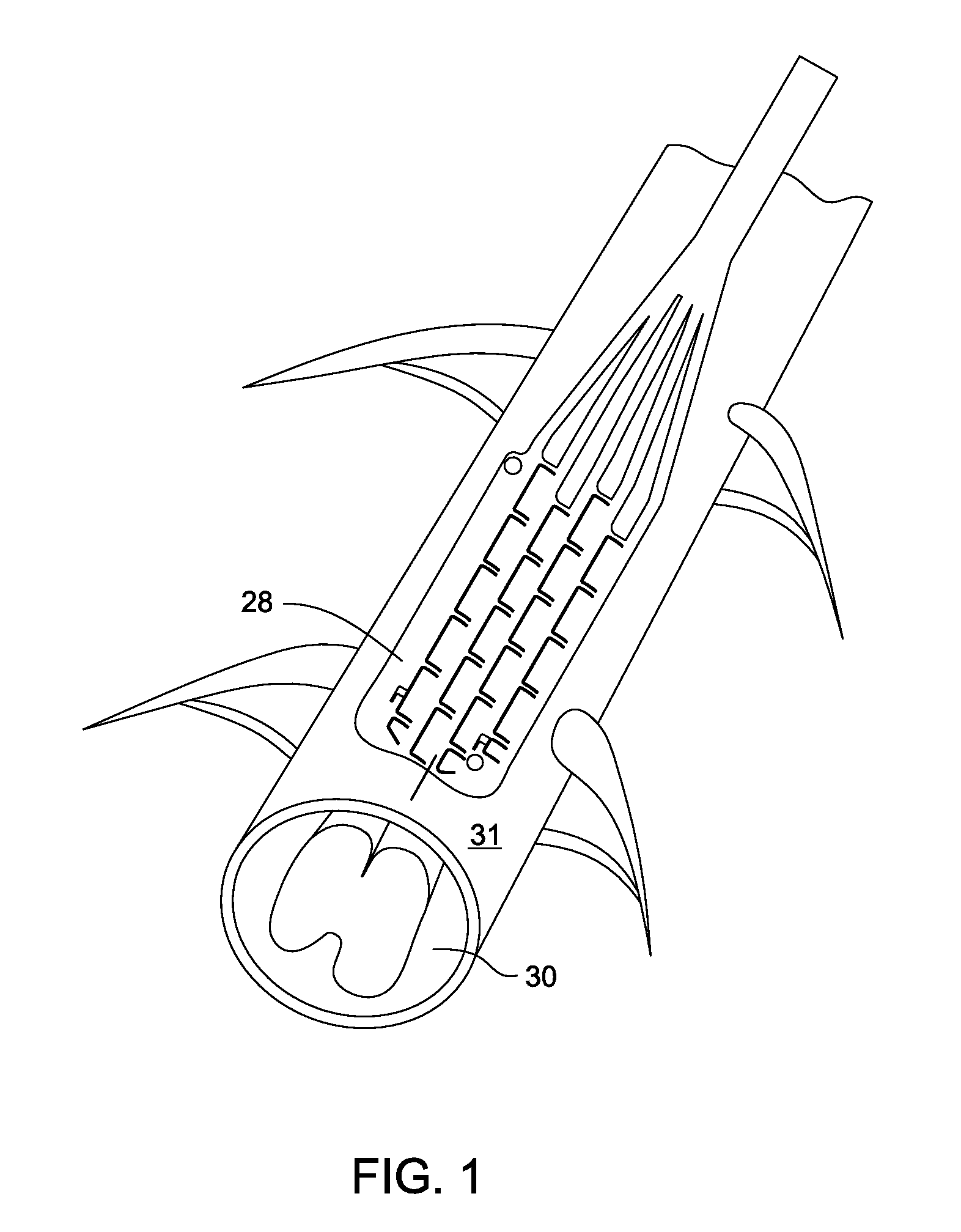
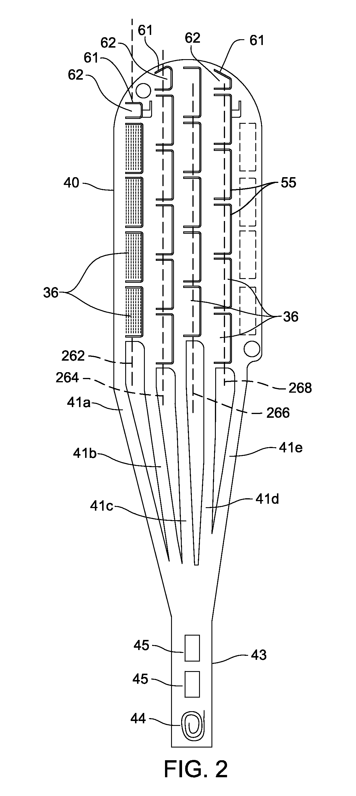
[0068]FIG. 1 is a perspective view of an electrode array assembly 28 of this invention disposed over a dura 31 that surrounds a spinal cord 30. As best seen in FIGS. 2-4, electrode array assembly 28 includes a frame 32, seen in FIGS. 3 and 4. Frame 32 is formed from a thin section of superelastic material that can be both formed and folded into non-linear shapes. Frame 32 supports a non-conductive substrate 34. Substrate 34 generally covers the whole of the surface of the frame 32. A number of spaced apart electrodes 36 are disposed on the substrate 34.

[0069]In the illustrated version of the invention, each electrode 36 is the shape of a rectangle with rounded corners. In FIG. 2A, for ease of illustration only four electrodes, the electrodes in the first column of electrodes (the column on the left side of the drawing) are illustrated. Also, the positions of the electrodes in the fifth column of electrodes (the column on the right side of the drawing), are...


PUM


Abstract

An electrode array assembly with a frame that is foldable or bendable on which electrodes are disposed. The frame includes laterally spaced apart bridges. Tabs extend laterally outwardly from the bridges Electrodes are disposed on the tabs. Beams, also part of the frame, extend between the laterally adjacent bridges. The frame can be folded around the beams so as to cause the laterally spaced bridges to at least partially overlap. When the beams are so bent, the electrode carrying tabs extend beyond the bent beams.

Description

RELATIONSHIPS TO EARLIER FIELD APPLICATIONS[0001]This application is a continuation of PCT Pat. App. No. PCT / US2009 / 033769 filed 11 Feb. 2009. PCT Pat. App. No. PCT / US2009 / 0033769 is a nonprovisional application that claims priority from U.S. Pat. Apps. No. 61 / 034,367 filed 6 Mar. 2008 and No. 61 / 139,395 filed 19 Dec. 2008. The contents of the application from which this application claims priority are now explicitly incorporated herein by reference.FIELD OF THE INVENTION[0002]This invention relates generally to an electrode array, with multiple electrodes, that can be minimally invasively implanted adjacent target tissue within a patient and a tool for implanting the electrode array.BACKGROUND OF THE INVENTION[0003]There are a number of medical conditions for which it has been found that an effective therapy involves driving current through a section of the tissue of a patient. Often, the current is driven between the electrodes of an electrode array implanted in the patient. Gener...

Claims


Application Information

Patent Timeline
Patent Type & Authority Applications(United States)
IPC IPC(8): A61N1/05A61B19/00
CPCA61N1/0553
Inventor JANIK, JOHN J.STAUNTON, DOUGLASBRINDLEY, ROBERT A.BOZUNG, TIMOTHY J.
Owner STRYKER CORP
Why Eureka
Try Eureka