Sonar transducer assembly having a printed circuit board with flexible element tabs

a technology of printed circuit board and sonar transducer, which is applied in the direction of sound producing devices, reradiation, acoustic wave reradiation, etc., can solve the problems of degrading sonar image, and achieve the effects of reducing the number of unfavorable signals

Active Publication Date: 2019-03-21
NAVICO HLDG
View PDF0 Cites 4 Cited by
  • Summary
  • Abstract
  • Description
  • Claims
  • Application Information

AI Technical Summary

Benefits of technology

[0005]When, for the purpose of producing an array of spatially-arranged receivers or transmitters, more than one transducer element is placed in a sonar system, it is desirable, in order to effectively apply simple beamforming algorithms, that the electrical signals transduced by the transducer elements be uniform simple functions of the acoustic field that they are intended to sample (in the case of receiving) or produce (in the case of transmitting). Physical connections between the transducer elements and the PCB may not only produce an undesired signal involving the PCB as an elastic wave-bearing medium, but the mechanical impedance of the connections may also have a local effect on the frequency response of the transducer elements, e.g. mass loading by solder at the attachment points of the transducer elements. Inconsistencies in the mechanical boundary conditions at the point of electrical connections in addition to the elastic response of the PCB may cause undesired, chaotic electrical signals to be produced by the transducer elements, which may, for example, degrade the sonar image.
[0006]Some embodiments of the present invention contemplate a flex tab arrangement for the PCB of a sonar transducer assembly. Such a flex tab arrangement may mitigate the undesired signals caused by the elastic response of the PCB. Additionally, the element-to-element variations across the transducer assembly caused by inconsistencies in the mechanical boundary conditions due to inconsistent solder joints may be mitigated by removing the solder connection altogether.
[0007]In some embodiments, the PCB may include a set of flexible electrical connection tabs for each transducer element, e.g. piezoelectric crystal. The transducer element may be inserted into a section of the PCB between the flex tabs, thereby causing the flex tabs to flex outwardly from a plane defined by the PCB. In some embodiments, the flexion of the flex tabs outwardly of the PCB plane may cause an elastic force on each of the flex tabs to be applied to opposing ends of the transducer elements to create an electrical connection. In some embodiments, the flexion of the flex tabs may mechanically isolate the ends of the transducer elements from the PCB, thereby mitigating or eradicating interference from the elastic response of the PCB.
[0008]In this regard, in some embodiments, the transducer elements may not be affixed, such as by solder or adhesive, to the PCB. Instead, the force applied by the flex tabs on opposing ends of the installed transducer element may be sufficient to maintain the position of the transducer element as well as maintain an electrical connection to the transducer element. The removal of the solder connection to the PCB may further eliminate transference of the resonance waves from the transducer elements to the PCB. Further, removal of the solder connection may also remove inconsistences in the mechanical boundary conditions of the electrical connections to the transducer elements, thereby reducing element-to-element variations across the transducer assembly and, in some cases, increasing the sharpness of the sonar image.

Problems solved by technology

Physical connections between the transducer elements and the PCB may not only produce an undesired signal involving the PCB as an elastic wave-bearing medium, but the mechanical impedance of the connections may also have a local effect on the frequency response of the transducer elements, e.g. mass loading by solder at the attachment points of the transducer elements.
Inconsistencies in the mechanical boundary conditions at the point of electrical connections in addition to the elastic response of the PCB may cause undesired, chaotic electrical signals to be produced by the transducer elements, which may, for example, degrade the sonar image.

Method used


Image

  • Sonar transducer assembly having a printed circuit board with flexible element tabs
  • Sonar transducer assembly having a printed circuit board with flexible element tabs
  • Sonar transducer assembly having a printed circuit board with flexible element tabs

Examples


Embodiment Construction

[0055]Exemplary embodiments of the present invention now will be described more fully hereinafter with reference to the accompanying drawings, in which some, but not all embodiments of the invention are shown. Indeed, the invention may be embodied in many different forms and should not be construed as limited to the exemplary embodiments set forth herein; rather, these embodiments are provided so that this disclosure will satisfy applicable legal requirements. Like reference numerals refer to like elements throughout.

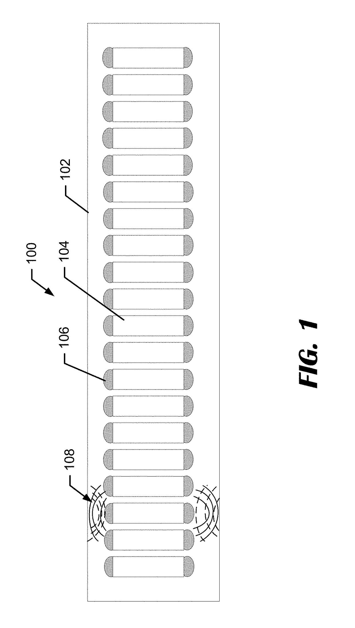
[0056]FIG. 1 illustrates an example transducer assembly 100. The transducer assembly 100 may include a printed circuit board (PCB) 102 and a plurality of transducer elements 104 arranged in an array. Each of the transducer elements 104 may be a piezoelectric crystal that is surface mounted to the PCB 102. In some embodiments, each of the transducer elements 104 may be directly affixed to the PCB 102, such as by a solder joint 106. The transducer elements 104 may each ha...


PUM


Abstract

An example sonar transducer assembly is provided including at least one transducer element and a flexible printed circuit board (PCB) including at least one set of electrical connections for the at least one transducer element. The electrical connections include flex tabs configured to flex out of a PCB plane. The sonar transducer assembly also includes a support structure including an aperture for the at least one transducer element. The support structure is configured to support the body of the PCB, allow flexion of the flex tabs into the aperture, and retain the at least one transducer element in the at least one aperture. The transducer element is installed in a direction that is perpendicular to the PCB plane causing the flex tabs to flex outwardly from the PCB plane, thereby creating an elastic force of the flex tabs applied against opposing ends of the at least one transducer element.

Description

FIELD OF THE INVENTION[0001]Embodiments of the present invention relate generally to sonar transducer assemblies, and more particularly, to sonar transducer assemblies having a printed circuit board with flexible element tabs configured to hold transducer elements.BACKGROUND OF THE INVENTION[0002]Sonar (SOund Navigation And Ranging) is used to detect waterborne or underwater objects. For example, sonar devices may be used to determine depth and bottom topography, detect fish, locate wreckage, etc. Sonar transducer elements, or simply transducers, convert electrical energy into sound or vibrations at a particular frequency. A sonar sound beam is transmitted into and through the water and is reflected from objects it encounters. The transducer receives the reflected sound (the “sonar returns”) and converts the sound energy into electrical energy. Based on the known speed of sound, it is possible to determine the distance to and / or location of the waterborne or underwater objects. The ...

Claims


Application Information

Patent Timeline
Patent Type & Authority Applications(United States)
IPC IPC(8): G01S15/89G01S7/521G10K11/00G10K11/35
CPCG01S15/89G01S7/521G10K11/008G10K11/352
Inventor PHILLIPS, ROGERANTAO, BARRY M.CASPALL, JAYME J.
Owner NAVICO HLDG
Why Eureka
Try Eureka