Grill and Method of Use Thereof

a technology of grille and nozzle, which is applied in the field of grille, can solve the problems of inability to create a flue effect to direct smoke away from the user towards the rear of the grille, inconvenient situation, dangerous situation, etc., and achieve the effect of preventing smoke from flowing into the user's fa

Active Publication Date: 2011-04-07
JACKOVITCH TIMOTHY
View PDF27 Cites 17 Cited by
  • Summary
  • Abstract
  • Description
  • Claims
  • Application Information

AI Technical Summary

Benefits of technology

Accordingly, a feature and advantage of the present invention is its ability to direct smoke in a rearward direction away from the user.
Another feature and advantage of the present invention is its ability to prevent smoke from flowing into a user's face.
Still another feature and advantage of the present invention is its ability to position the second grill door at different angles.
Yet another feature and advantage of the present invention is its ability to control two grill doors by only lifting the main grill handle.
Yet still another feature and advantage of the present invention is its ability to provide a shield against smoke that is blown into a user's face by wind.
Still another feature and advantage of the present invention is its ability to directionally control smoke exiting from the grill.

Problems solved by technology

In order to open the door, however, the user has to stand relatively close to the front of the grill, and upon opening the door, the user is met with a blast of hot smoke.
Such a situation is not only inconvenient, but also dangerous, as a user may inhale hot and intense smoke fumes.
While such a device creates an opening through which smoke escapes, it lacks the ability to create a flue effect to direct smoke away from the user towards the rear of the grill when the grill cover is in an open position.
While such a device covers the opening of a grill, the glass panel is not taught to be removable during the cooking process, and is only taught to be removable for cleaning purposes.
Further, such a device lacks the ability to be positioned at different angles and lacks the ability to create a flue that moves smoke to the rear of the grill as the smoke exits.

Method used


Image

  • Grill and Method of Use Thereof
  • Grill and Method of Use Thereof
  • Grill and Method of Use Thereof

Examples


Embodiment Construction

In describing the preferred and selected alternate embodiments of the present invention, as illustrated in FIGS. 1-6C, specific terminology is employed for the sake of clarity. The invention, however, is not intended to be limited to the specific terminology so selected, and it is to be understood that each specific element includes all technical equivalents that operate in a similar manner to accomplish similar functions.

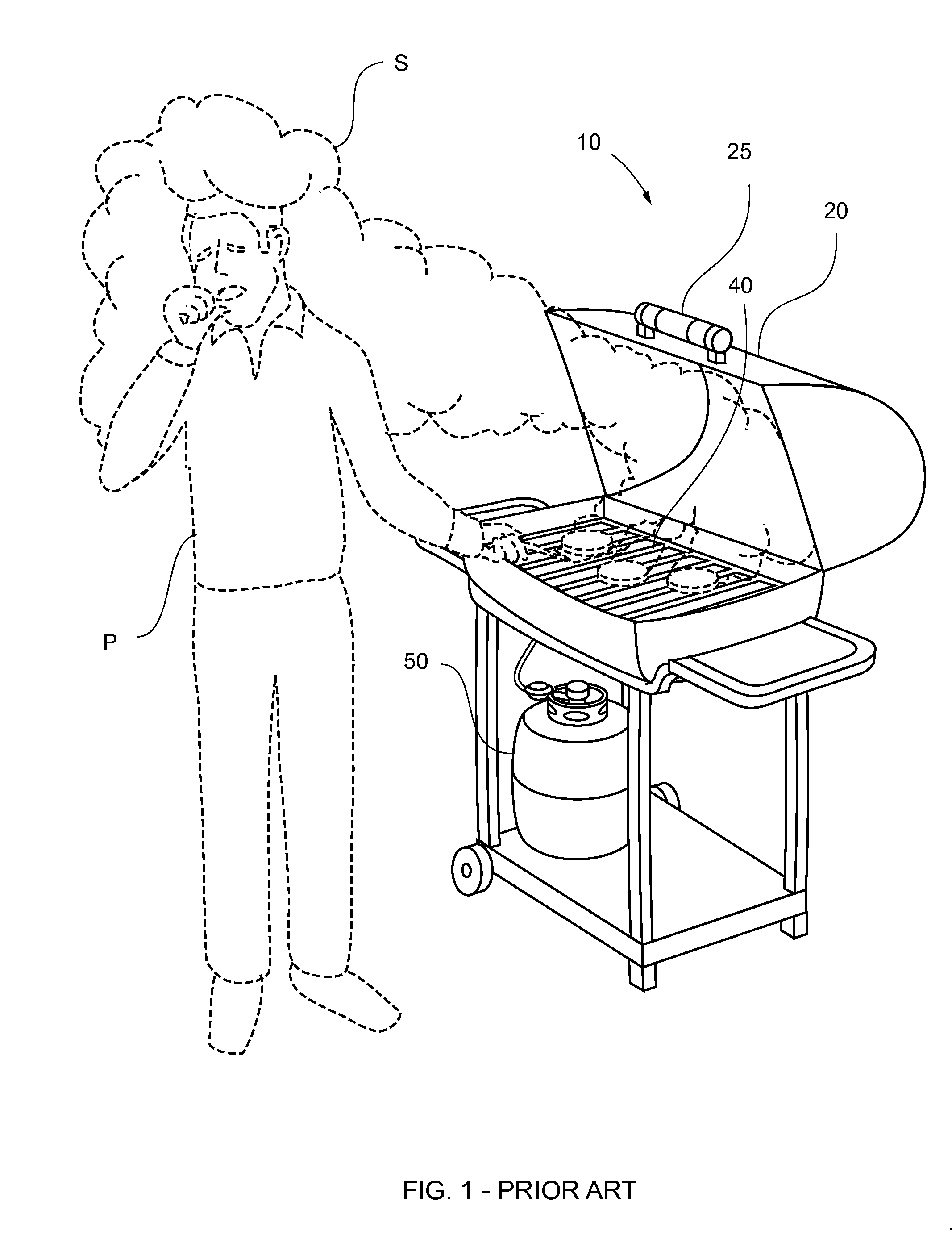
Referring now to FIG. 1, depicted therein is prior art embodiment grill 10, wherein grill 10 comprises lid 20, grate 40 and propane tank 50. Lid 20 comprises front handle 25, wherein front handle 25 is utilized to selectively open and close lid 20. In use, person P opens lid 20 to access grate 40, wherein person P stands near grate 40 to cook food. Accordingly, person P is in direct contact with smoke S while cooking food on grate 40, thereby causing person P undesirable smoke inhalation and distress during the grilling process. This inhalation and distress is part...


PUM


Abstract

A grill comprising a front, a rear, a grill base, a grill lid and a grill door. The grill lid comprises an opening and is in hinged communication with the grill base. The grill door communicates with the grill lid via a hinge, which is disposed at a rear portion of the opening. When the grill door is closed, the grill door seals the opening in the grill lid. The grill lid includes a lifting-assist mechanism and the grill door has an opening-assist mechanism. A method of grilling comprising the steps of opening the grill lid, placing food on the grill base and closing the grill lid to cook food. The method further comprises the steps of opening the grill lid and the grill door during the cooking process, thereby creating a flue that urges smoke away from the front of the grill and towards the rear of the grill.

Description

FEDERALLY SPONSORED RESEARCH OR DEVELOPMENTNonePARTIES TO A JOINT RESEARCH AGREEMENTNoneREFERENCE TO A SEQUENCE LISTINGNoneBACKGROUND OF THE INVENTION1. Technical Field of the InventionThe present invention relates generally to a grill and method of use thereof, and more specifically to a grill having a spring-assisted secondary grill door that forms a hinged opening in the typical grill lid, wherein the grill lid is spring-assisted, and wherein the secondary grill door when open forms a flue that directs smoke away from the front of the grill and toward the rear of the grill.2. Description of Related ArtBarbeque pits are desirable for many occasions that require food to be cooked outdoors, such as family reunions, picnics, barbeques and company functions. Most available grills contain a door, which is opened to remove or add food to the grill, or to check on the cooking progress of the food. In order to open the door, however, the user has to stand relatively close to the front of ...

Claims


Application Information

Patent Timeline
Patent Type & Authority Applications(United States)
IPC IPC(8): A47J37/07F23M7/00
CPCA47J37/07A47J37/0786A47J36/06F24C15/2007
Inventor JACKOVITCH, TIMOTHY
Owner JACKOVITCH TIMOTHY
Why Eureka
Try Eureka