
Seal moldings for vehicles

a technology for sealing molding and vehicles, applied in mechanical equipment, roofs, transportation and packaging, etc., can solve the problems of vehicle exposure to water, particulates, wind,

Active Publication Date: 2011-04-07
GM GLOBAL TECH OPERATIONS LLC
View PDF13 Cites 2 Cited by
  • Summary
  • Abstract
  • Description
  • Claims
  • Application Information

AI Technical Summary

Benefits of technology

The present invention provides a seal molding that can minimize the gap between a vitreous element and a body panel of a vehicle, resulting in a better seal and a more aesthetically pleasing appearance. The seal molding is easy to install and compatible with different vehicle designs. It is cost-effective and can be used with non-staggered-edge vitreous elements. The technical effects of the invention are improved vehicle design and a more seamless transition between the vitreous element and the body panel.

Problems solved by technology

Vehicles may be exposed to water, particulates, and wind during operation.

Method used


Image

  • Seal moldings for vehicles
  • Seal moldings for vehicles
  • Seal moldings for vehicles

Examples


second embodiment

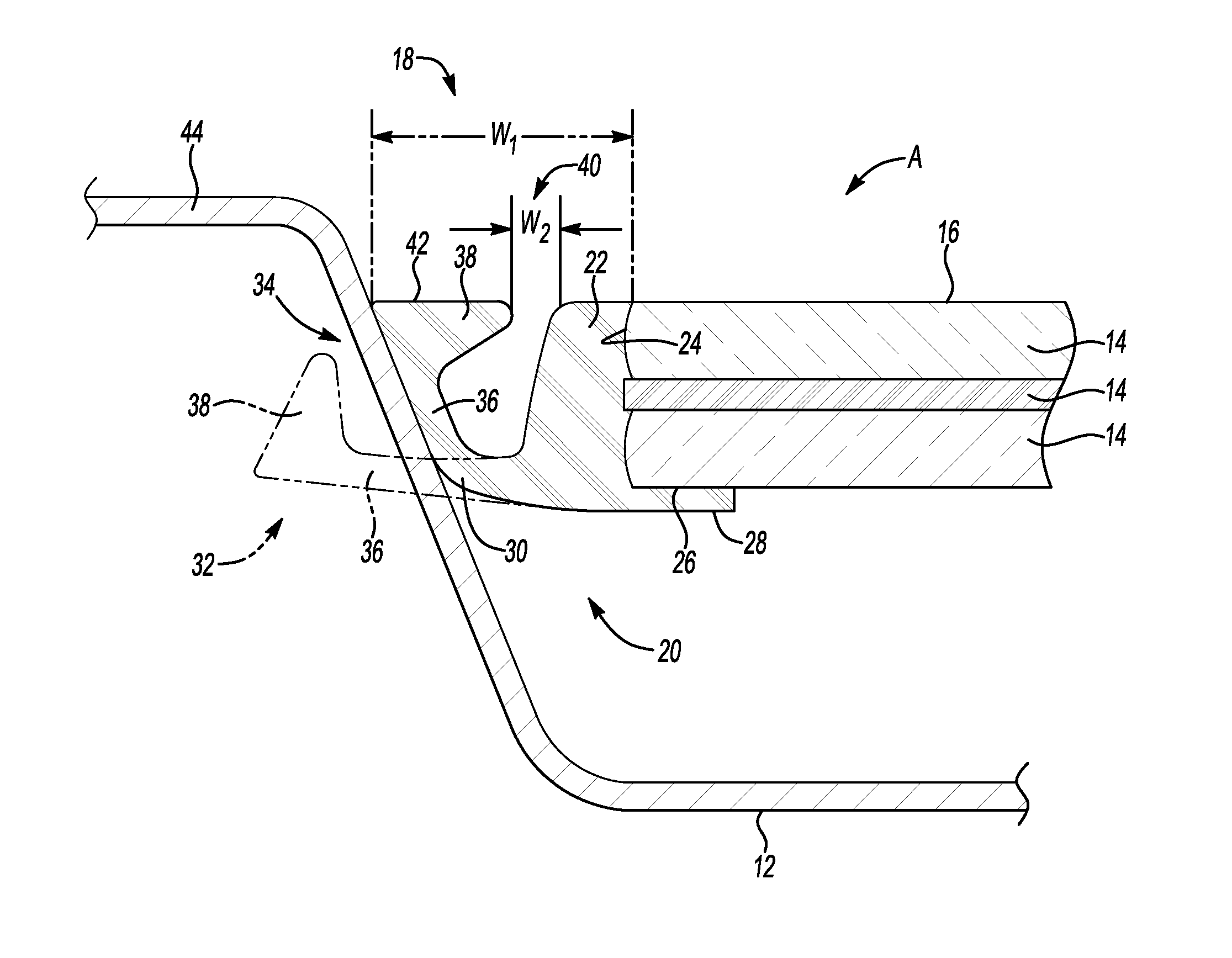
[0030]Referring to FIG. 4, in the seal molding 120, the first portion 122 of the seal molding 120 may include a ledge 46 protruding from the first portion 122. The ledge 46 may be configured for concealing a portion of the first perceivable gap 18 between the vitreous element 14 and the body panel 12. The ledge 46 may have any suitable shape, length, width, and / or thickness, and may protrude from any location on the first portion 122. For this embodiment, the second portion 30 may be sufficiently juxtaposed with respect to the ledge 46 to thereby minimize the first perceivable gap 18. For example, the second portion 30 may overhang the ledge 46. That is, as the second portion 30 is flexed toward the first portion 122, the protrusion 38 may be sufficiently juxtaposed with respect to the ledge 46. Therefore, when viewed from the direction of arrow B in FIG. 4, the ledge 46 may further conceal or restrict a portion of the first perceivable gap 18, as set forth in more detail below. Sin...

third embodiment

[0031]Referring now to FIG. 5, in the seal molding 220, the seal molding 220 includes a first portion 222 configured for abutting the vitreous element 14, as set forth above. The first portion 222 also includes a sill 48 projecting from the first portion 222. In this embodiment, the second portion 230 is configured for abutting the body panel 12, as set forth above, and includes an elongated flexible segment 236 and a protrusion 238 projecting away from the elongated flexible segment 236 and shaped to mate with the sill 48. For example, the sill 48 may be complementarily-shaped with the protrusion 238 so as to mate with and support the protrusion 238 when the second portion 230 flexes and abuts the body panel 12. Stated differently, the sill 48 may be configured for supporting the protrusion 238.

[0032]The second portion 230 is configured for flexing toward and abutting the sill 48 to reduce and thereby minimize the first perceivable gap 18 between the vitreous element 14 and the bod...


PUM


Abstract

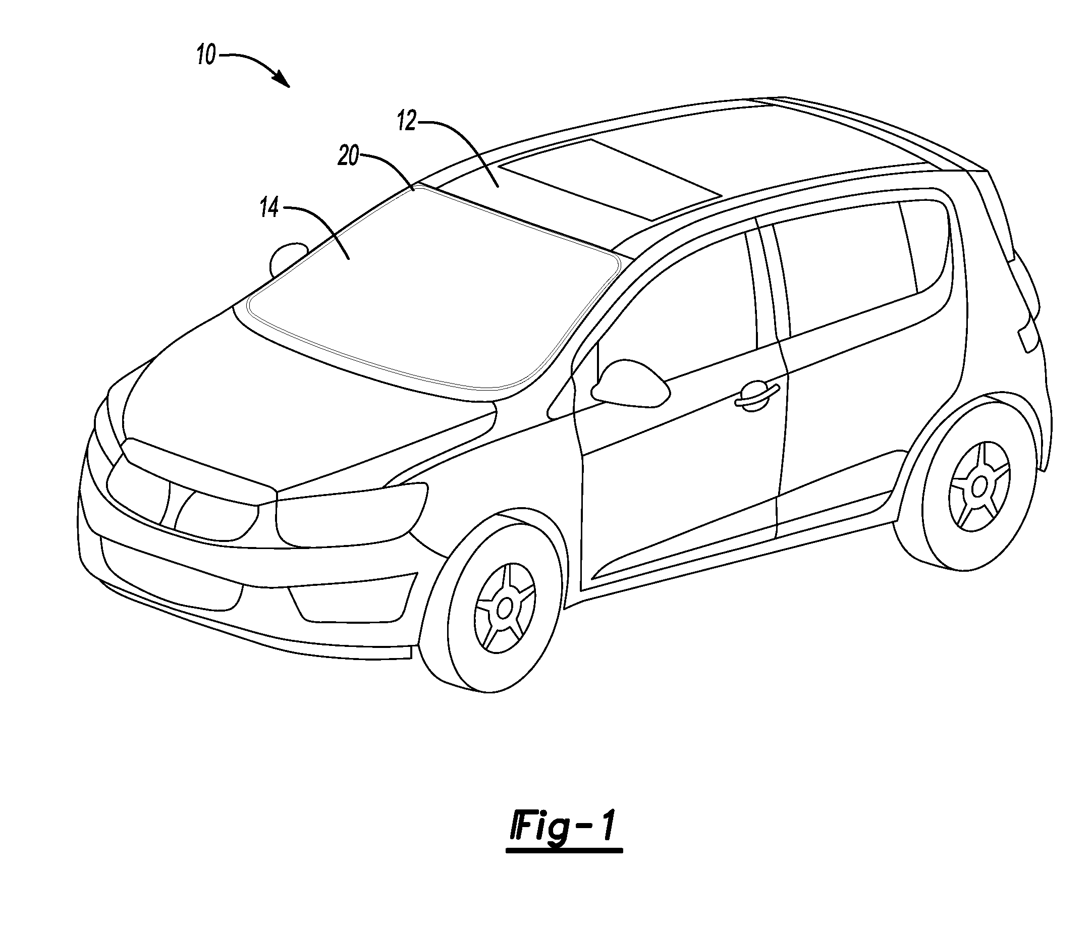
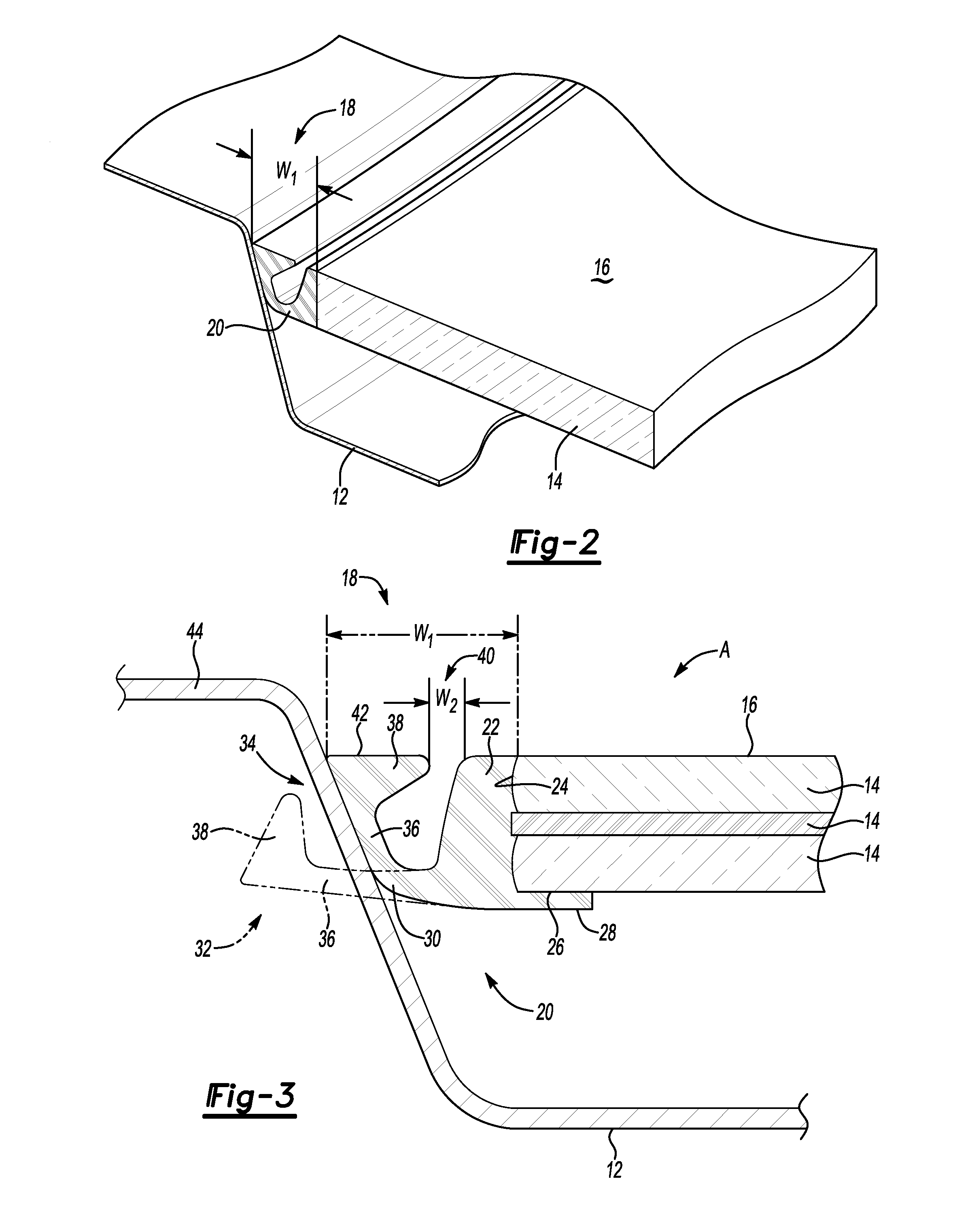
A seal molding configured for minimizing a first perceivable gap having a first width between a vitreous element and a body panel of a vehicle includes a first portion configured for abutting the vitreous element and a second portion configured for abutting the body panel and including an elongated flexible segment and a protrusion projecting away from the segment. The second portion is configured for flexing toward the first portion to define an alternative gap having a second width that is smaller than the first width to thereby minimize the first perceivable gap between the vitreous element and the body panel. A vehicle includes a body panel, a vitreous element having an outer surface and spaced apart from the body panel to define the first perceivable gap, and the seal molding disposed between and in contact with the vitreous element and the body panel.

Description

TECHNICAL FIELD[0001]The present invention generally relates to trim moldings for vehicles, and more specifically, to a seal molding of a vehicle.BACKGROUND OF THE INVENTION[0002]Vehicles may be exposed to water, particulates, and wind during operation. Therefore, a seal between a vitreous element of the vehicle, such as a windshield, and a body panel of the vehicle, such as a roof deck, is desirable to maintain a dry, clean, and quiet cabin for occupants. Similarly, such seals between other vitreous elements of the vehicle, such as headlight housings, and other body panels of the vehicle, such as fascias, are desirable to maintain a dry and clean housing for vehicle components. Seal moldings often provide both the desired seal and a perceivable transition between the vitreous element and the body panel.SUMMARY OF THE INVENTION[0003]A seal molding configured for minimizing a first perceivable gap having a first width between a vitreous element and a body panel of a vehicle includes ...

Claims


Application Information

Patent Timeline
Patent Type & Authority Applications(United States)
IPC IPC(8): B60J10/02F16J15/02B60J10/00B60J1/02B60J1/10
CPCB60J10/02B60J10/70
Inventor RENKE, DAVID T.HAGEN, THOMAS D.MOHIUDDIN, GULAMWALTERS, GARY L.
Owner GM GLOBAL TECH OPERATIONS LLC
Learn More