System and Method for User Equipment Measurement Timing in a Relay Cell

a relay cell and user equipment technology, applied in the field of wireless communication, can solve the problems of significant number of times when the user equipment may not receive any data, and the transmission of rn-to-donor enb on the same time-frequency resource may not be feasible, so as to minimize the impact of the prohibition of the two patterns on the ues and minimize the loss of transmission opportunities

Active Publication Date: 2011-04-07
FUTUREWEI TECH INC
View PDF6 Cites 33 Cited by
  • Summary
  • Abstract
  • Description
  • Claims
  • Application Information

AI Technical Summary

Benefits of technology

[0014]An advantage of an embodiment is that by overlapping a first subframe pattern with a second subframe pattern to minimize a loss of transmission opportunities, the impact of the prohibitions of the two patterns on the UEs is minimized.

Problems solved by technology

Therefore, due to the RN's transmitter causing interference to its own receiver, simultaneous “donor eNB-to-RN” and “RN-to-UE” or “UE-to-RN” and “RN-to-donor eNB” transmissions on the same time-frequency resource may not be feasible unless sufficient isolation of outgoing and incoming signals is provided, e.g., by means of specific, well separated, and well isolated antenna structures.
Hence, there may be a significant number of times when the UE may not receive any data due to the MBSFN subframes and the measurement gaps.

Method used


Image

  • System and Method for User Equipment Measurement Timing in a Relay Cell
  • System and Method for User Equipment Measurement Timing in a Relay Cell
  • System and Method for User Equipment Measurement Timing in a Relay Cell

Examples


Embodiment Construction

[0025]The making and using of the embodiments are discussed in detail below. It should be appreciated, however, that the present invention provides many applicable inventive concepts that can be embodied in a wide variety of specific contexts. The specific embodiments discussed are merely illustrative of specific ways to make and use the invention, and do not limit the scope of the invention.

[0026]The present invention will be described with respect to preferred embodiments in a specific context, namely a 3GPP LTE compliant communications system with relay nodes. The invention may also be applied, however, to other communications systems with relay nodes, such as WiMAX, and so on, compliant communications systems.

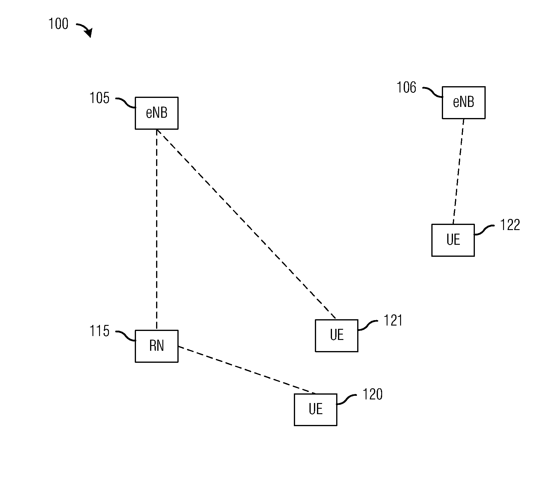
[0027]FIG. 1 illustrates a communications subsystem 100. Communications subsystem 100 includes several eNBs, such as eNB 105 and eNB 106. Communication subsystem 100 also includes a RN 115. As discussed earlier, a RN may be used to improve data transfer rates, mobility, cov...


PUM


Abstract

A system and method for user equipment (UE) measurement timing in a relay cell are provided. A method for controller operations includes broadcasting a first pattern of time intervals to communications devices served by a controller, and for a communication device served by the controller, determining a second pattern for the communications device, where the second pattern is based on the first pattern, and transmitting the second pattern to the communications device.

Description

[0001]This application claims the benefit of U.S. Provisional Application No. 61 / 248,733, filed on Oct. 5, 2009, entitled “System and Method for User Equipment Measurement Timing in a Relay Cell,” which application is hereby incorporated herein by reference.TECHNICAL FIELD[0002]The present invention relates generally to wireless communications, and more particularly to a system and method for user equipment (UE) measurement timing in a relay cell.BACKGROUND[0003]A relay node (RN) is considered as a tool to improve, e.g., the coverage of high data rates, group mobility, temporary network deployment, the cell-edge throughput and / or to provide coverage in new areas. The RN is wirelessly connected to a wireless communications network via a donor cell (also referred to as a donor enhanced Node B (donor eNB or D-eNB)).[0004]There may be several kinds of RNs, one kind serves as an eNB to one or more User Equipment (UE). A wireless link between the RN and its served UEs is referred to as an...

Claims


Application Information

Patent Timeline
Patent Type & Authority Applications(United States)
IPC IPC(8): H04L27/00
CPCH04L27/0006H04B7/2606
Inventor BLANKENSHIP, YUFEILIU, DEPINGCHEN, XIANG
Owner FUTUREWEI TECH INC
Why Eureka
Try Eureka