Expansion anchor

a technology of expansion sleeves and expansion sleeves, applied in the direction of fastening means, dowels, mechanical equipment, etc., can solve the problems of low initial static friction and hinder the expansion sleeves, and achieve the effects of improving the adhesion of the expansion sleeves, improving the friction, and simple and economical production

Inactive Publication Date: 2011-04-07
HILTI AG
View PDF7 Cites 29 Cited by
  • Summary
  • Abstract
  • Description
  • Claims
  • Application Information

AI Technical Summary

Benefits of technology

[0022]For purposes of simple and economical production of the expansion anchor, the expansion cone is advantageously made of metal by a cold-molding process. It is also advantageous for the expansion cone to be provided with an indentation on its end facing away from the expansion sleeve, as a result of which, on the one hand, material is saved during the production of the expansion body and, on the other hand, a compartment is formed for the drilling dust and drilling debris that collects at the bottom of the drilled hole.
[0023]The expansion sleeve is advantageously made of sheet steel in a stamping / bending process. In order to improve the adhesion of the expansion sleeve to the wall of the drilled hole, the outside of the expansion sleeve is advantageously provided with a structure and especially advantageously with elevations projecting towards the outside that increase the friction between the expansion sleeve and the wall of the drilled hole, thus preventing undesired turning of the expansion sleeve, especially at the beginning of the process of installing the expansion anchor.

Problems solved by technology

Moreover, the low initial static friction hinder or prevents the expansion sleeve from turning along in the drilled hole at the beginning of the installation process or when the expansion body starts to be pulled into the expansion sleeve.

Method used


Image

  • Expansion anchor
  • Expansion anchor
  • Expansion anchor

Examples


Embodiment Construction

[0032]Fundamentally, the same parts are designated with the same reference numerals in the figures.

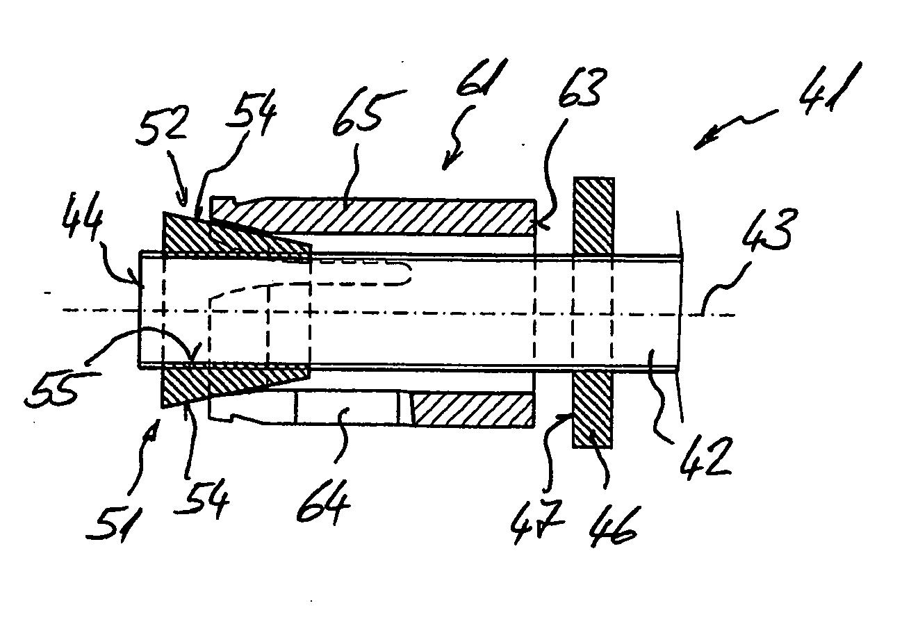
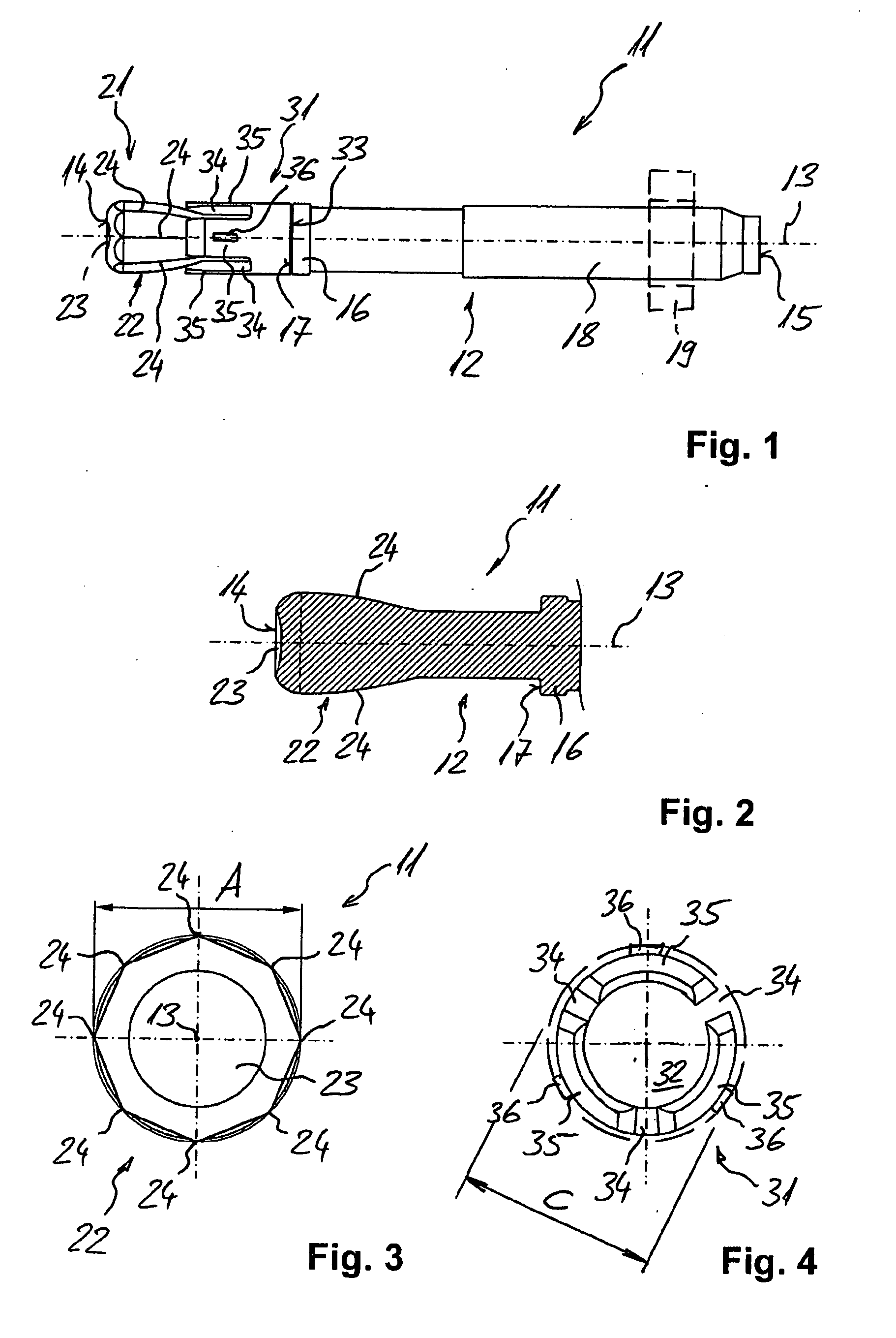
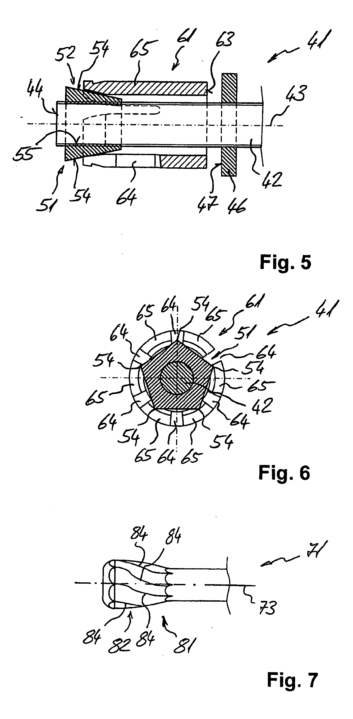
[0033]The multi-part expansion anchor 11 shown in FIGS. 1 through 4 comprises a stud body 12 with a longitudinal axis 13 whose first end 14 has an expansion body 21 as well as—adjacent thereto in the direction of the second end 15 of the stud body 12—an expansion sleeve 31 that defines an interior 32. Adjacent to the second end 15, the stud body 12 has a threaded section 18 for a nut 19 indicated here by a broken line.

[0034]As its elements, the expansion sleeve 31—as a first part of the expansion anchor 11—has three, that is to say, an odd number of expansion tabs 35 separated from each other by lengthwise slots 34. The expansion sleeve 31 surrounds areas of the stud body 12 adjacent to the expansion body 21. At a distance from the expansion body 21, the stud body 12 has a shoulder 16 that forms a stop portion 17 for the expansion sleeve 31 on one end 33 of the expansion sleeve 31 faci...


PUM


Abstract

A multi-part expansion anchor (11) has, as a first part, an expansion sleeve (31) which has, as its elements, several expansion tabs (35) that are separated from each other by elongated slots (34) and has, as a second part, an expansion body (21) that can be pulled into the expansion sleeve (31), and a conical portion (22) for purposes of radially widening the expansion sleeve (31). The conical portion (22) has, as its elements, edges (24) running along the longitudinal axis (13). One of the parts of the expansion anchor (11) has an even number of appropriate elements, while the other part of the expansion anchor (11) has an odd number of appropriate elements.

Description

[0001]This claims the benefit of German Patent Application DE 10 2009 045 345.8, filed Oct. 6, 2009 and hereby incorporated by reference herein.[0002]The invention relates to a multi-part expansion anchor.BACKGROUND[0003]Such multi-part expansion anchors are used in a drilled hole that has been previously made in a substrate, for example, in a wall, floor or ceiling of a structure. When the expansion body is pulled into the expansion sleeve, the latter is widened radially and the expansion anchor is anchored in the substrate.[0004]European patent application EP 1 243 801 B1 discloses a multi-part expansion anchor that, as a first part, has an expansion sleeve which has, as its elements, several expansion tabs that are separated from each other by elongated slots and that, as a second part, has an expansion body that can be pulled into the expansion sleeve and that has a conical portion for purposes of radially widening the expansion sleeve, whereby the conical portion has, as its el...

Claims


Application Information

Patent Timeline
Patent Type & Authority Applications(United States)
IPC IPC(8): F16B13/06
CPCF16B13/0858F16B13/065F16B13/066
Inventor WISSLING, MATTHIASSCHAEFFER, MARC
Owner HILTI AG
Why Eureka
Try Eureka