Denture

a technology for dentures and teeth, applied in dental prosthetics, dental surgery, instruments, etc., can solve the problems of no explicit information from dentists, prone to misplaced and lost removable dentures,

Inactive Publication Date: 2011-04-07
CHINA MEDICAL UNIVERSITY(TW)
View PDF2 Cites 80 Cited by
  • Summary
  • Abstract
  • Description
  • Claims
  • Application Information

AI Technical Summary

Problems solved by technology

However, the removable denture is apt to be misplaced and lost, especially in hospitals and nursing homes.
Additionally, dentists have no explicit information to realize the conditions of use of the denture to facilitate further correction of the patients' habit of using the denture, and early treatment of the patients.

Method used


Image

  • Denture
  • Denture
  • Denture

Examples


Embodiment Construction

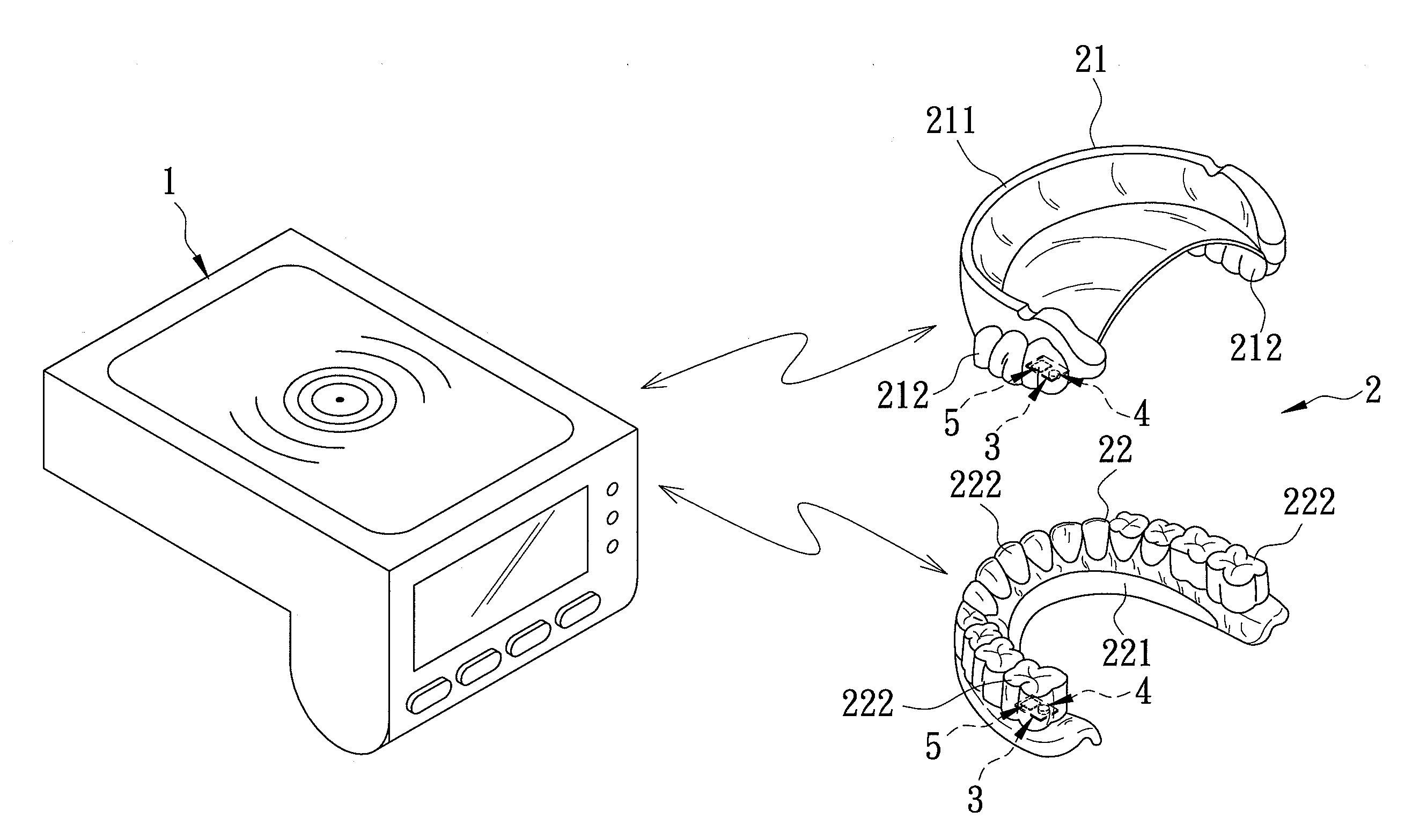
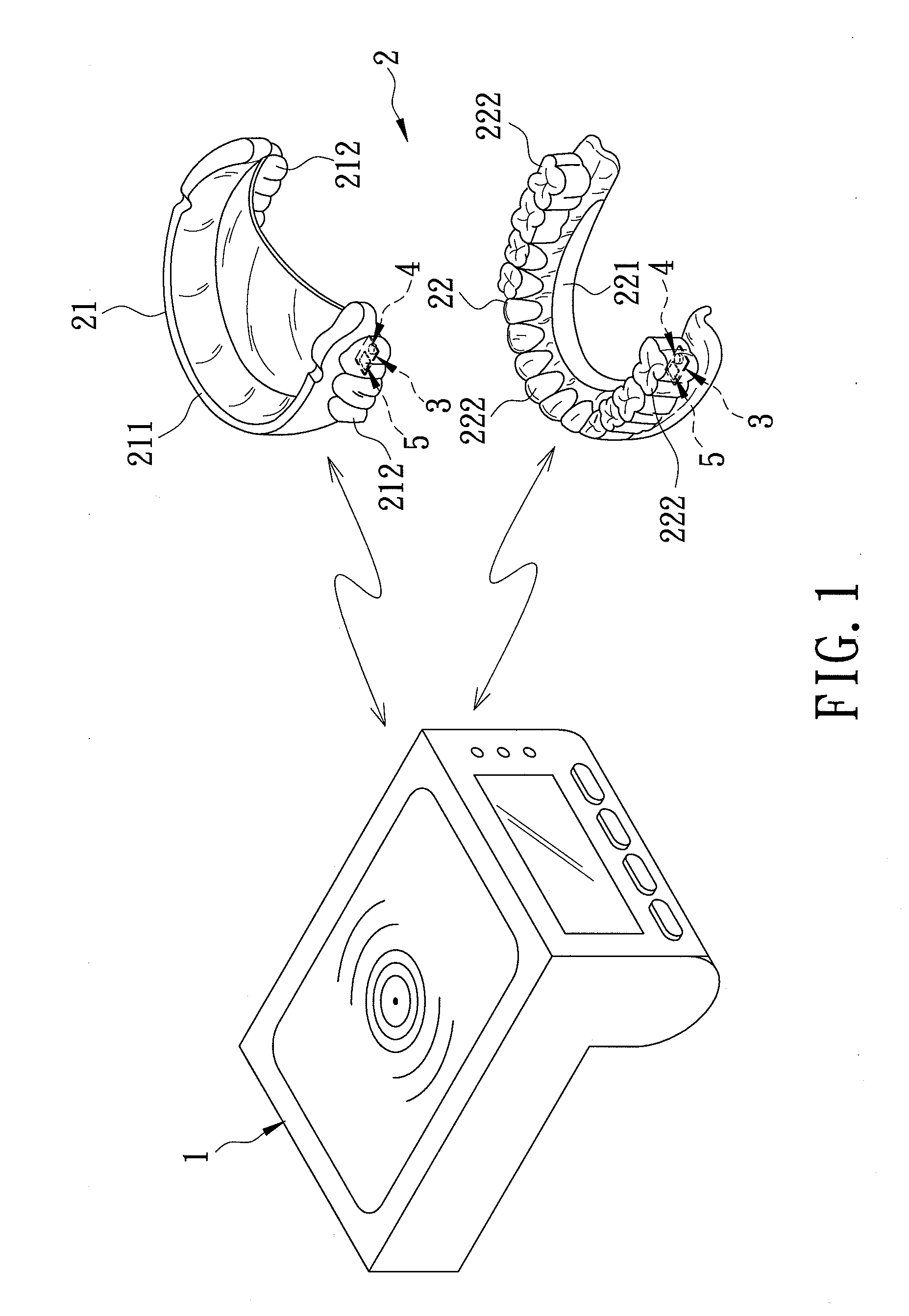
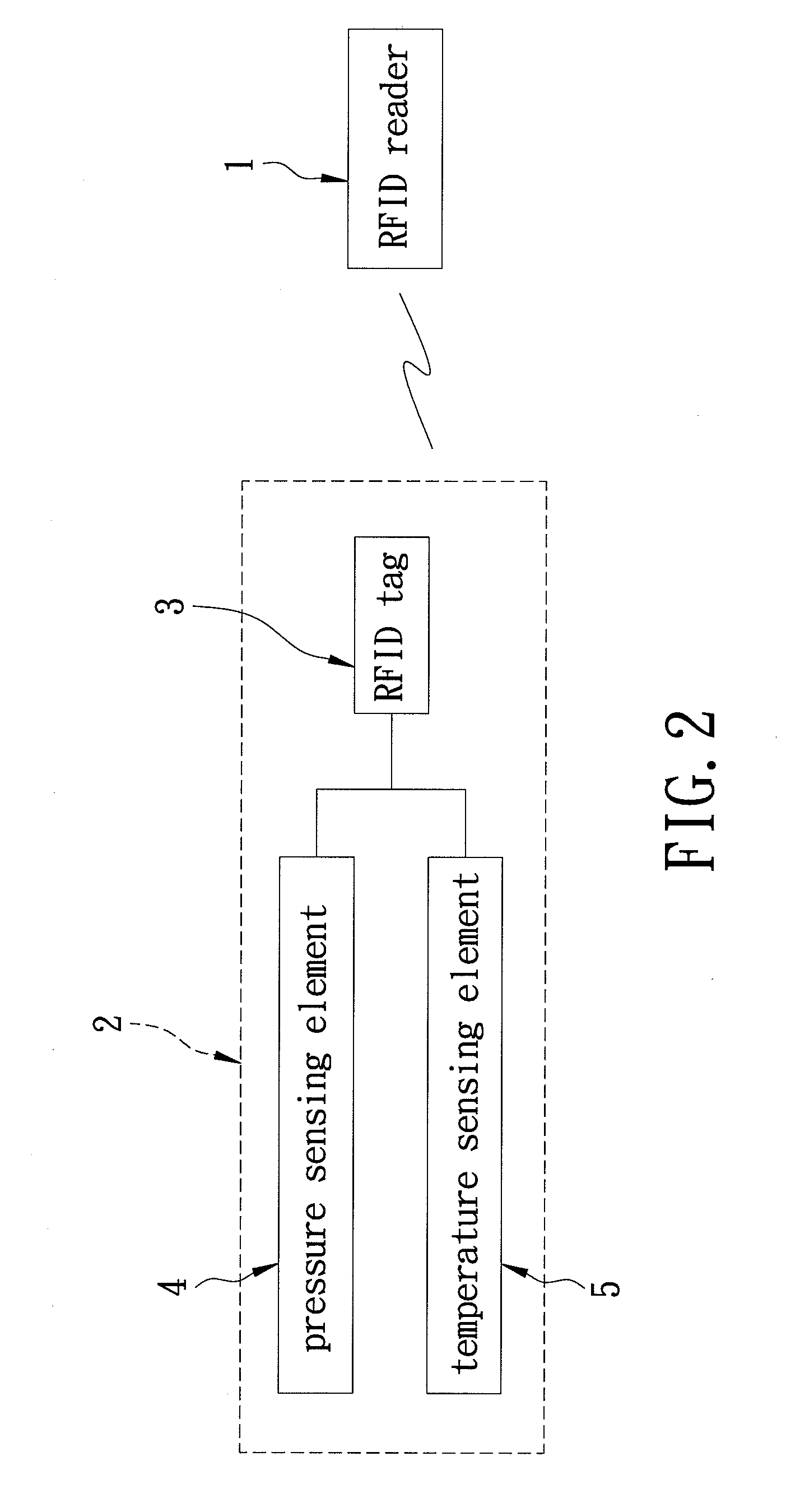
[0011]As shown in FIGS. 1 and 2, a preferred embodiment of a denture according to the present invention is adapted to communicate with a radio frequency identification (RFID) reader 1. The denture comprises a denture main body 2, two RFID tags 3, two pressure sensing elements 4, and two temperature sensing elements 5.

[0012]The denture main body 2 has an upper tooth portion 21 and a lower tooth portion 22. Each of the upper and lower tooth portions 21, 22 has a gum 211, 221, and a plurality of teeth 212, 222 implanted on the gum 211, 221.

[0013]The RFID tags 3 are embedded respectively in the upper tooth portion 21 and the lower tooth portion 22 of the denture main body 2 for storage of identification information of a user of the denture.

[0014]Each of the pressure sensing elements 4 is embedded in one of the teeth 212, 222 of a respective one of the upper tooth portion 21 and the lower tooth portion 22 of the denture main body 2. The pressure sensing elements 4 are electrically connec...


PUM


Abstract

A denture is adapted to communicate with a radio frequency identification (RFID) reader. The denture includes a denture main body and at least one RFID tag embedded in the denture main body for storage of identification information of a user of the denture. The RFID tag transmits the information to the RFID reader by radio frequency wave.

Description

BACKGROUND OF THE INVENTION[0001]1. Field of the Invention[0002]The invention relates to a denture, more particularly to a denture adapted to communicate with a radio frequency identification (RFID) reader.[0003]2. Description of the Related Art[0004]Patients suffering from tooth decay, periodontal disease, and elders need to wear a partial denture or a complete denture. The partial denture and complete denture must be removed and cleaned after meals and at sleep time to ensure healthy oral cavity and gum.[0005]However, the removable denture is apt to be misplaced and lost, especially in hospitals and nursing homes. Additionally, dentists have no explicit information to realize the conditions of use of the denture to facilitate further correction of the patients' habit of using the denture, and early treatment of the patients.SUMMARY OF THE INVENTION[0006]Therefore, the object of the present invention is to provide a denture capable of alleviating the above drawbacks of the prior ar...

Claims


Application Information

Patent Timeline
Patent Type & Authority Applications(United States)
IPC IPC(8): A61C13/08
CPCA61C2204/005A61C13/01G08B21/24
Inventor FUH, LIH-JYH
Owner CHINA MEDICAL UNIVERSITY(TW)
Why Eureka
Try Eureka