

Safety structure for covering syringe needle
- Summary
- Abstract
- Description
- Claims
- Application Information
AI Technical Summary
Benefits of technology
Problems solved by technology
Method used
Image

Examples
Embodiment Construction
[0020]The present invention will now be described with some preferred embodiments thereof. For the purpose of easy to understand, elements that are the same in the preferred embodiments are denoted by the same reference numerals.
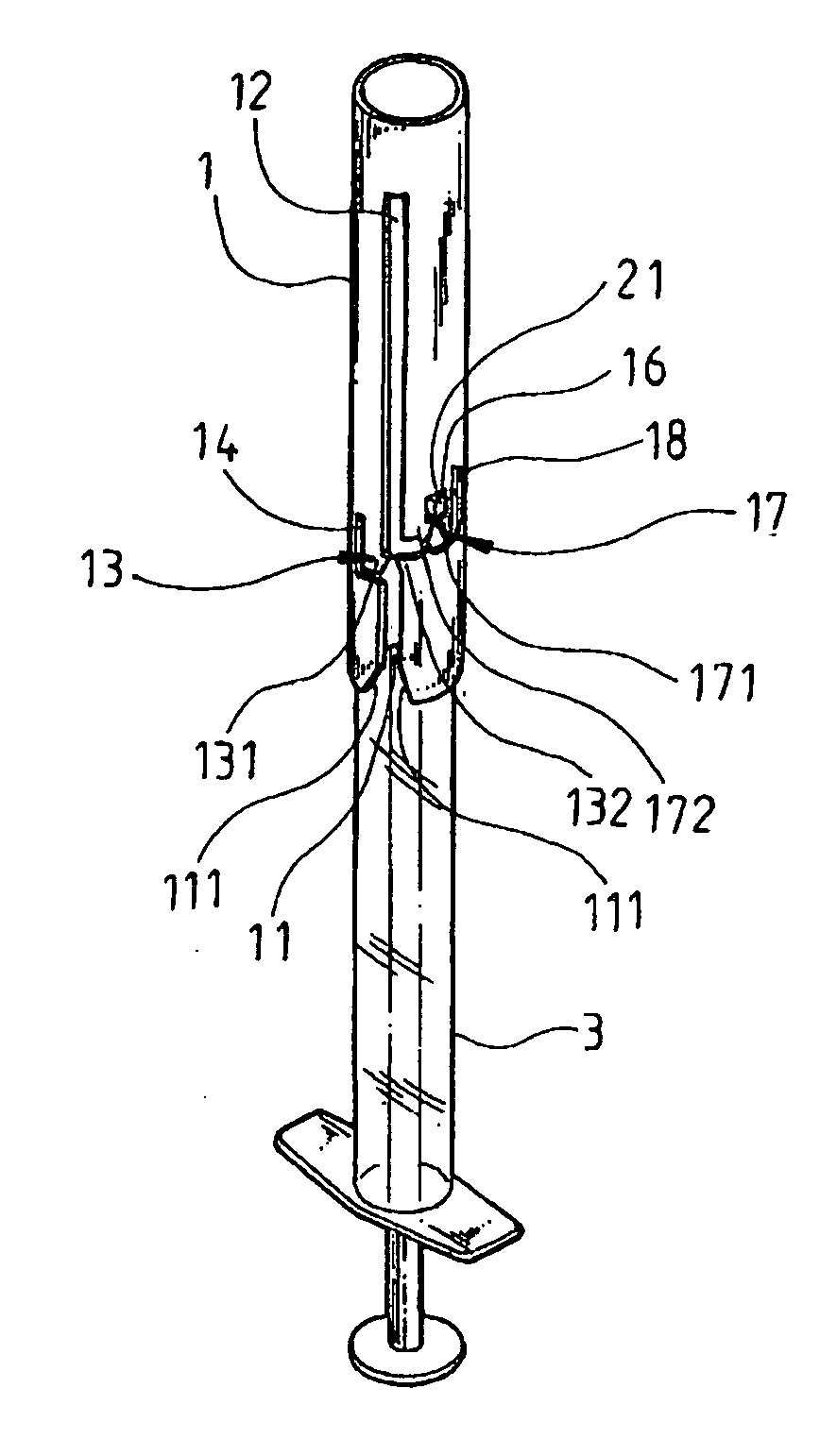
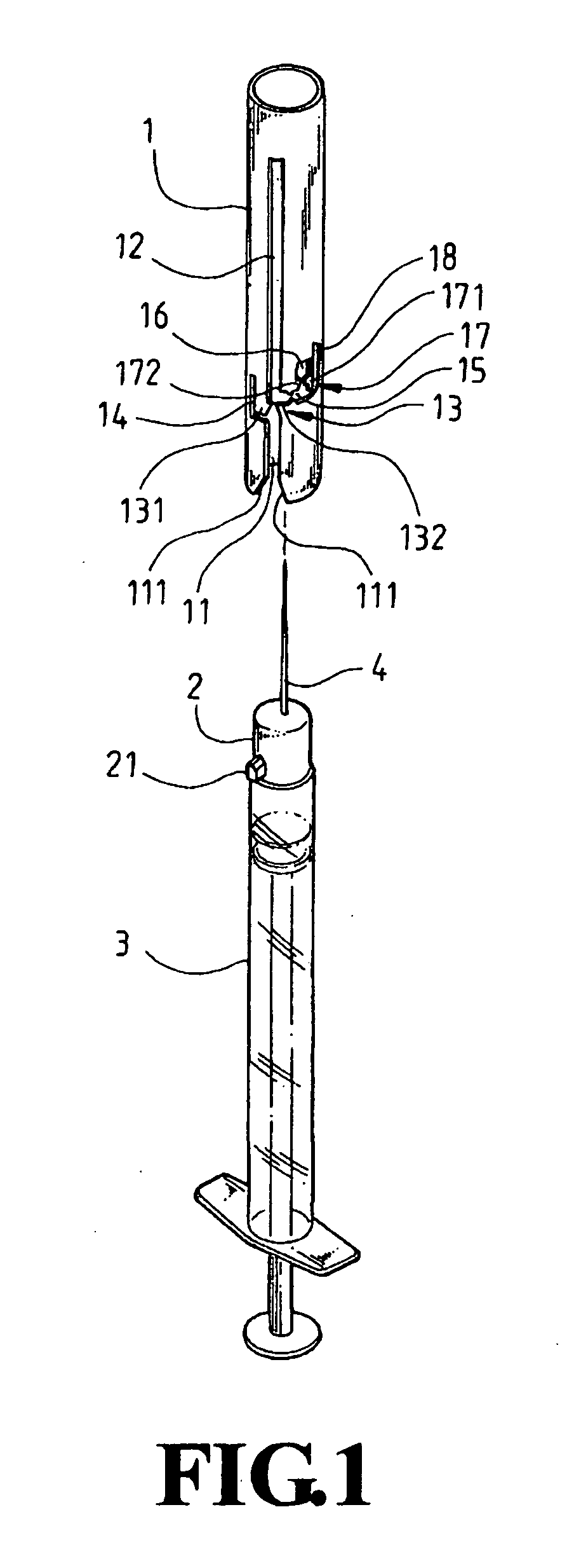
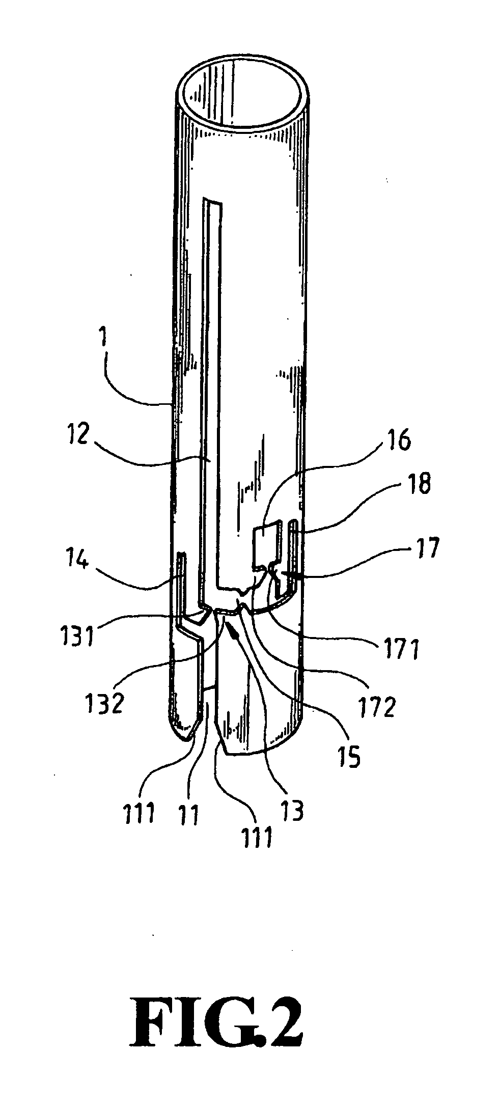
[0021]Please refer to FIG. 1 that is an exploded perspective view showing a safety structure for covering syringe needle according to the present invention. As shown, the safety structure includes a safety sleeve 1 and a needle hub 2 provided at a predetermined position with a radially outward projection 21. Please also refer to FIG. 2 that is a perspective view of the safety sleeve 1 according to a first embodiment thereof. As shown, the safety sleeve 1 in the first embodiment is provided at a rear open end with a cutout 11, a rearmost end of which is expanded to provide two beveled lateral edges 111, and a front end of which is axially extended forward by a predetermined length to form a longitudinal sliding slot 12 on the safety sleeve 1. A stop section 1...
PUM
 Abstract
Description
Claims
Application Information