Cutting blade for morcellator

a morcellator and cutting blade technology, applied in the field of surgical devices and methods, can solve the problems of affecting the use effect of the morcellator, so as to reduce the chances of the morcellator becoming dull or damaged during use.

Inactive Publication Date: 2011-04-07
ETHICON INC
View PDF4 Cites 40 Cited by
  • Summary
  • Abstract
  • Description
  • Claims
  • Application Information

AI Technical Summary

Benefits of technology

[0012]It is an object of the present invention to provide a morcellator cutting blade which minimizes the chances of the blade becoming dull or damaged during use.
[0013]It is another object of the present invention to provide a cutting blade for a morcellator which minimizes the chance of transected tissue morsels from becoming dislodged within the morcellator.
[0014]It is yet a further object of the present invention to provide a cutting blade for a morcellator which may be at least partially formed from less expensive materials than those used in conventional morcellators.
[0016]In accordance with one form of the present invention, a cutting blade for a morcellator is generally cylindrical in shape and includes a sidewall having an inner surface and an outer surface and which defines an axial bore radially inwardly of the inner surface thereof. The inner surface and the outer surface of the cutting blade at least partially reside in concentric cylindrical planes. The inner surface includes a sloped or beveled portion situated at a distal end of the cutting blade, which slope portion extends toward the outer surface in the direction of the distal end of the cutting blade to define a sharpened edge at the intersection of the inner and outer surfaces. The sharpened edge preferably resides in the cylindrical plane of the outer surface of the cutting blade. The sloped or beveled edge of the inner surface is provided to engage the tenaculum if it is not obvious to the surgeon that the tenaculum claws are spread to such an extent that they will contact the cutting blade. Under such circumstances, the tenaculum will contact the sloped or beveled edge of the inner surface of the cutting blade, rather than the sharpened edge, and therefore not dull or damage the sharpened edge of the cutting blade.
[0017]In another form of the present invention, the cutting blade is formed of two sections. The first section, the distal end of the cutting blade, is formed with a sharpened edge having a first diameter, and the second section which is situated adjacent to the distal end portion of the cutting blade has an inner surface having a second diameter. The second diameter of the second section is greater than the first diameter of the sharpened edge of the distal end portion of the cutting blade so that transected tissue morsels cut by the rotating distal end portion of the cutting blade should not become dislodged from the tenaculum or cause undue friction with the inner surface of the cutting blade as the tenaculum pulls the tissue morsel through the axial bore of the rotating cutting blade of the morcellator.

Problems solved by technology

Another difficulty sometimes encountered with known morcellators is that during use, whether by coring or orange peeling, the amount of tissue being withdrawn can cause friction within the inner rotating tube or to the seal system during removal.
The larger the tissue sections or strips, the more exaggerated this problem becomes.
In addition to friction encountered during tissue removal, manipulation of the grasping instrument within the rotating inner tube can interfere with the blade rotation and tends to lead to dulling of the blade with known morcellators, since the sharp edge is positioned on the inner most point on the circumference of the inner tube.
Removal and reinsertion of trocars and laparoscopic instruments during a given procedure is awkward and time consuming, and creates additional trauma at the site.

Method used


Image

  • Cutting blade for morcellator
  • Cutting blade for morcellator
  • Cutting blade for morcellator

Examples


Embodiment Construction

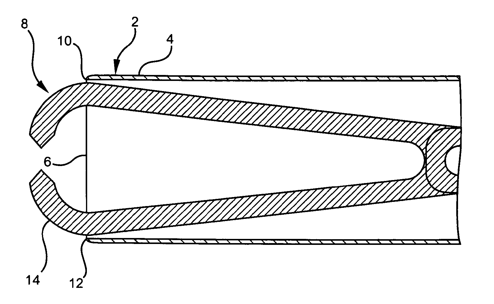
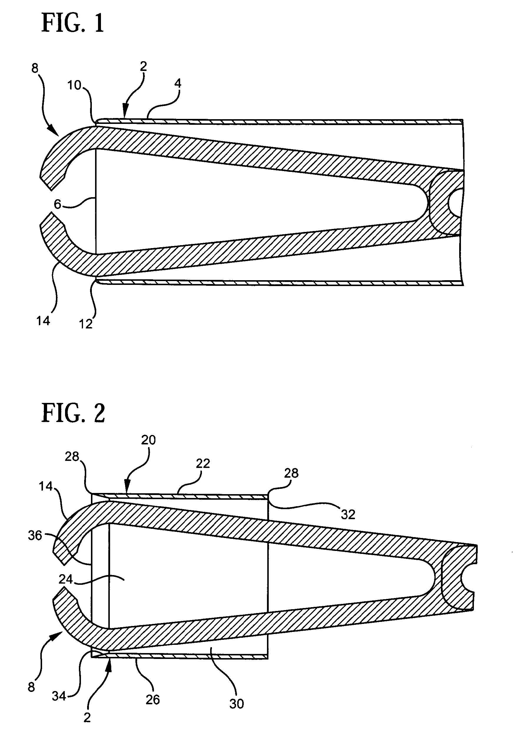
[0033]To facilitate an understanding of the present invention, reference should be made to FIG. 1 of the drawings, which shows the distal end 2 of a cutting blade 4 of a conventional morcellator. The morcellator has a cylindrical cutting blade 4 that rotates within an outer fixed tube or sleeve (not shown). The cutting blade 4 defines an axial bore 6 in which is selectively received a tissue grasping tool, or tenaculum 8. The exposed cutting edge 10 of the conventional morcellator blade 4 is sharpened in the cylindrical plane of the radially inner surface 12 of the cutting blade, as can be seen in FIG. 1.

[0034]The tenaculum 8 includes two expandable grasping claws or hooks 14 which are intended to grasp the tissue of an anatomical body (e.g., organ) and pull the tissue toward the rotating cutting blade 4 of the morcellator so that it may be cut into tissue “morsels”. The claws 14, after grasping tissue between them, may be in an expanded or spread state, as the tenaculum 8 is pulled...


PUM


Abstract

A cutting blade for a surgical morcellator has a distal end and a sharpened cutting edge situated at the distal end for transecting tissue to form tissue morsels, the cutting blade being structured to minimize contact between the sharpened edge and a tissue grasping instrument used with the morcellator during a surgical procedure. The cutting blade includes a generally cylindrically-shaped sidewall defining an axial bore for the passage of transected tissue morsels therethrough, the sidewall having an outer surface residing generally in a first cylindrical plane, an inner surface residing generally in a second cylindrical plane, and a sloped surface, the inner surface of the sidewall being disposed radially inwardly of the outer surface of the sidewall, the sloped surface extending transversely between the inner surface and the outer surface in the direction of the distal end of the cutting blade and joining the outer surface at an acute angle to define with the outer surface the sharpened cutting edge, the sharpened cutting edge residing in the first cylindrical plane in which the outer surface of the sidewall generally resides, wherein the sloped surface of the cutting blade sidewall extends radially inwardly beyond the second cylindrical plane in which the inner surface of the cutting blade sidewall generally resides to define a circular protrusion situated radially inwardly of the inner surface for selective engagement with the tissue grasping instrument used with the morcellator during a surgical procedure.

Description

CROSS REFERENCE TO RELATED APPLICATIONS[0001]The present application is a continuation of U.S. patent application Ser. No. 11 / 502,340, filed Aug. 10, 2006. The disclosure of the above-identified patent application is hereby incorporated by reference herein.BACKGROUND OF THE INVENTION[0002]1. Field of the Invention[0003]The present invention relates generally to surgical devices and methods, and more particularly to a laparoscopic morcellator having a detachable handle and various other improved features.[0004]2. Description of the Related Art[0005]Minimally invasive surgical procedures, such as laparoscopic procedures, have become very common. These procedures typically involve one or more small incisions that provide access to the relevant internal organ or tissue. A trocar, cannula or the like is placed into each incision, and all surgical steps are subsequently performed with instruments passed through or into the trocar(s).[0006]Many times it is desirable to remove relatively la...

Claims


Application Information

Patent Timeline
Patent Type & Authority Applications(United States)
IPC IPC(8): A61B17/32
CPCA61B17/32002A61B17/32053A61B2017/320775A61B2017/320024A61B17/3207A61B17/22A61B17/32
Inventor NOHILLY, MARTIN J.MIKSZA, ANTHONY S.NERING, ROBERT
Owner ETHICON INC
Why Eureka
Try Eureka