Mobile device charging base, and mobile device and charging base system

a mobile device and charging base technology, applied in electric vehicles, transportation and packaging, electric power, etc., can solve the problems of insufficient charging of mobile devices, inability to electromagnetically coupling induction coils to power supply coils, and inability to appropriately charge batteries. to achieve the effect of using dead space, reducing the possibility of losing the spacer not in use, and improving the usability of the charging bas

Inactive Publication Date: 2011-04-14
SANYO ELECTRIC CO LTD
View PDF3 Cites 25 Cited by
  • Summary
  • Abstract
  • Description
  • Claims
  • Application Information

AI Technical Summary

Benefits of technology

[0013]In order to solve the aforementioned disadvantage, the present applicant has developed a charging base 10C shown in FIGS. 21 and 22. This charging base 10C has a mount portion 12C to which a mobile device 50 is mounted. The mount portion 12C has a curved bottom surface 13C that has a U-shaped groove. A power supply coil 21C is arranged inside the curved bottom surface 13C, and can be electromagnetically coupled to an induction coil 51C of the mobile device 50. Since the bottom surface of the mount portion is curved, in the case where the mobile device 50 has a curved back surface, when the mobile device 50 is put into the mount portion, the mobile device 50 will be guided by its own weight so that the curved back surface is positioned in the bottom of the curved bottom surface. According to this charging base, the induction coil included inside the curved bottom surface can be always brought in proximity to the power supply coil. Accordingly, electric power can be efficiently transmitted to the induction coil from the power supply coil. As a result, it is possible to quickly charge the battery.
[0027]In a mobile device and charging base system according to an eleventh aspect of the present invention, an option unit OU can be coupled to the device case of the mobile device 50. In addition, the mount portion 12 of the charging base 10 can be designed so that the power supply coil 21 is electromagnetically coupled to the induction coil 51 when the mobile device 50 with the option unit OU coupled thereto is placed on the mount portion 12. The mount portion 12 of the charging base 10 can receive a spacer 90 that adjusts the position of the mobile device 50 so that the power supply coil 21 is electromagnetically coupled to the induction coil 51 even when the mobile device 50 without the option unit OU is placed on the mount portion 50. According to this mobile device and charging base system, even in the entire length of a mobile device is changed by attachment / detachment of the option unit, since the size of the mount portion can be changed by shifting the bottom of the mount portion upward / downward by attachment / detachment of the spacer, it is possible to appropriately charge a battery of the smaller mobile device with or without the option unit.

Problems solved by technology

If the mobile device is not placed at a predetermined position, a battery of the mobile device may not be appropriately charged.
H09-68655 has a disadvantage in that the battery pack cannot be charged if the battery pack is deviated from a predetermined position when placed on the charging base.
The reason is that, if the battery pack is deviated from the predetermined position relative to the charging base, the induction coil cannot be not electromagnetically coupled to the power supply coil.
However, the system disclosed in Japanese Utility Model Publication No. 3011829 has a disadvantage in that users feel it troublesome to guide the positioning protruding portion into the positioning recessed portion when placing the mobile device onto the charging base.
Also, this system has another disadvantage in that users cannot always appropriately place the mobile device onto the charging base.
In addition, since the positioning recessed portion is formed on the bottom surface of a case and the induction coil is arranged above the positioning recessed portion, this system has another disadvantage in that the mobile device cannot be configured thinner.
For this viewpoint, since the positioning recessed portion increase the thickness of a mobile device, the positioning recessed portion may cause inconvenience when users carry the mobile device.
However, in this case, since the magnetic field is generated even in a part of the upper surface of the charging base where the mobile device is not placed, there is a disadvantage in that the electric power efficiency is reduced that is transmitted from the power supply coil to the induction coil.
In addition, there is another disadvantaged in that, if metal such as iron is placed on the charging base, heat may be generated by a current produced in the metal by magnetic induction.

Method used


Image

  • Mobile device charging base, and mobile device and charging base system
  • Mobile device charging base, and mobile device and charging base system
  • Mobile device charging base, and mobile device and charging base system

Examples


case 11a

(Upper Base Case 11A)

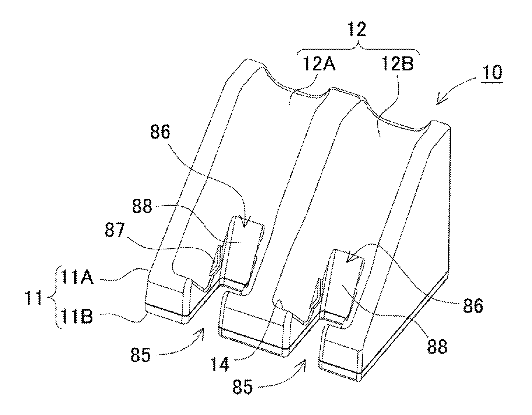
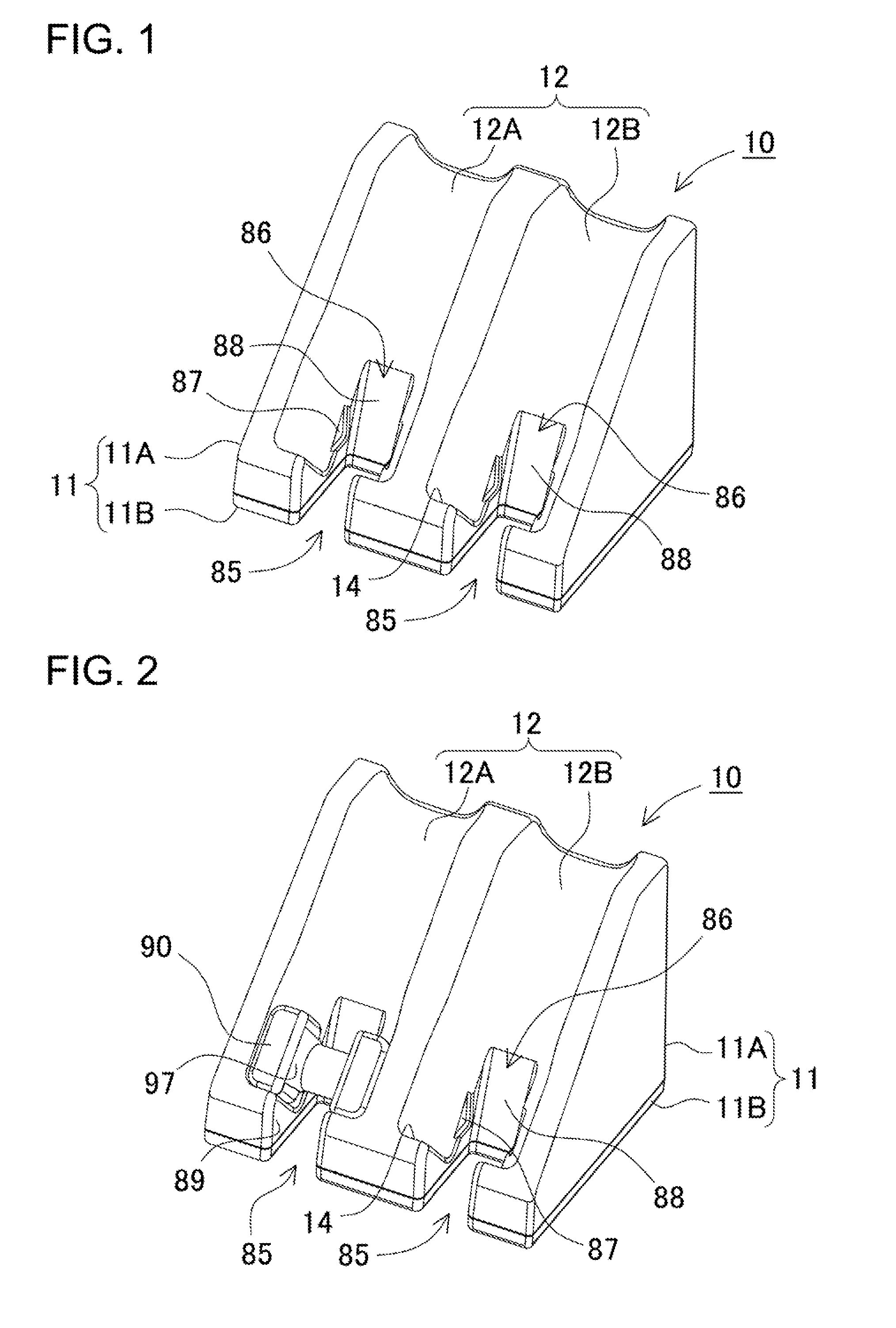
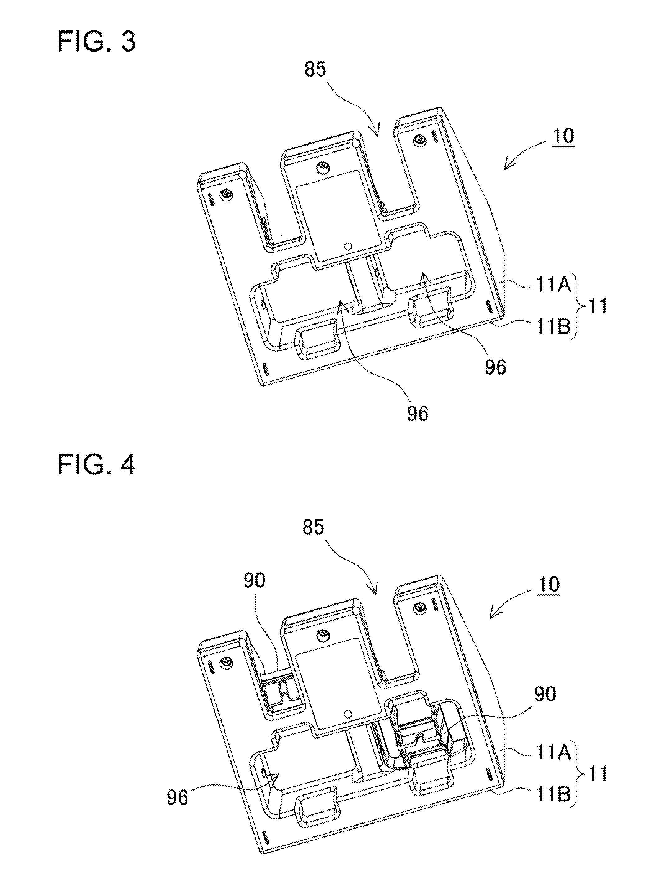
[0074]The charging base 10 is now described. Charging bases 10 shown in FIGS. 1 to 20 have the mount portion 12 on the upper base case 11A. The mount portion 12 of the upper base case 11A has a U-shaped groove as a curved bottom surface 13. In the mount portion 12 of the illustrated upper base case 11A, the longitudinal direction of the curved bottom surface 13 of U-shaped groove is inclined upward toward the back of the upper base case 11. The stopper wall 14 is arranged on the lower end of the mount portion 12. This mount portion 12 has a U-shaped groove in a cross-sectional view as viewed from the longitudinal direction of the mount portion 12. Accordingly, the mount portion 12 can accurately guide the mobile device 50 to a predetermined position. This upper base case 11A is formed of plastic by molding in a shape that provides a pair of side walls 15 on the both sides of the mount portion 12, and the stopper wall 14 on the lower end of the mount portion 12.

[...


PUM


Abstract

A charging base for charging a mobile device includes an induction coil and a battery pack. The pack includes a battery charged by the induction coil. The base includes a base case, a mount portion, a power supply coil, and a power supply. The mount portion is recessed on the surface of the case, and can detachably hold the device. The power supply coil is arranged in proximity to and inside the recessed bottom surface of the mount portion to be electromagnetically coupled to the induction coil, and connected to the power supply coil. A cut-out portion is formed in a surface of the mount portion by partially cutting out the case to communicate with the outside. This surface intersects a mount surface of the device.

Description

BACKGROUND OF THE INVENTION[0001]1. Field of the Invention[0002]The present invention relates to a mobile device that includes a rechargeable battery, and a charging base that charges this mobile device.[0003]2. Description of the Related Art[0004]So-called non-contact charging bases have been developed that transmit electric power from a power supply coil to an induction coil through electromagnetic induction and charge a battery included in a mobile device (see Japanese Patent Laid-Open Publication No. H09-63655 and Japanese Utility Model Publication No. 3011829).[0005]JP H09-63655-A discloses a system composed of a charging base including a power supply coil that can be energized by a high-frequency power supply, and a battery pack including an induction coil that is electromagnetically coupled to the power supply coil. The battery pack further includes a circuit that rectifies an altering current induced by the induction coil and provides the rectified current to its battery so ...

Claims


Application Information

Patent Timeline
Patent Type & Authority Applications(United States)
IPC IPC(8): H02J7/00
CPCH02J7/0044
Inventor TOYA, SHOICHIMORITA, HIDEYOSASAJI, KATSUAKI
Owner SANYO ELECTRIC CO LTD
Why Eureka
Try Eureka