
Compression garments with heel elevation

a compression garment and heel technology, applied in the field of compression garments, can solve the problems of affecting the cardiovascular circulation, causing pressure ulcers, and affecting the healing effect of patients, and achieve the effect of reducing or mitigating the pressure on the heel of an individual

Inactive Publication Date: 2011-04-14
SUN SCI
View PDF62 Cites 116 Cited by
  • Summary
  • Abstract
  • Description
  • Claims
  • Application Information

AI Technical Summary

Benefits of technology

"The invention is a compression garment with an elevation member for elevating the heel while applying compressive pressure to the lower leg. The garment includes a backing member with a compression bladder and an elevation member. The elevation member can be inflated to elevate the heel while the compression bladder compresses the lower leg. The invention also includes a cushioning member to reduce pressure on the heel. The technical effects of the invention include reducing pressure on the heel while improving blood flow and promoting better circulation in the lower leg."

Problems solved by technology

The condition can be life-threatening if a blood clot migrates to the lung, resulting in a pulmonary embolus or otherwise interfering with cardiovascular circulation.
Hospitalized patients, when in bed for a prolonged period of time, have a tendency to form pressure ulcers.
In many cases, the patient may already be predisposed to ulcer formation because of, for example, reduced circulation, and may require compressive therapy outside of a hospital.
Heel ulcers are costly and, if not treated promptly and properly, may lead to osteomyelitis and even limb amputation.

Method used


Image

  • Compression garments with heel elevation
  • Compression garments with heel elevation
  • Compression garments with heel elevation

Examples


Embodiment Construction

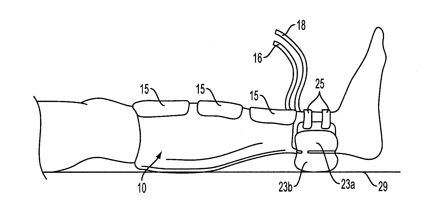
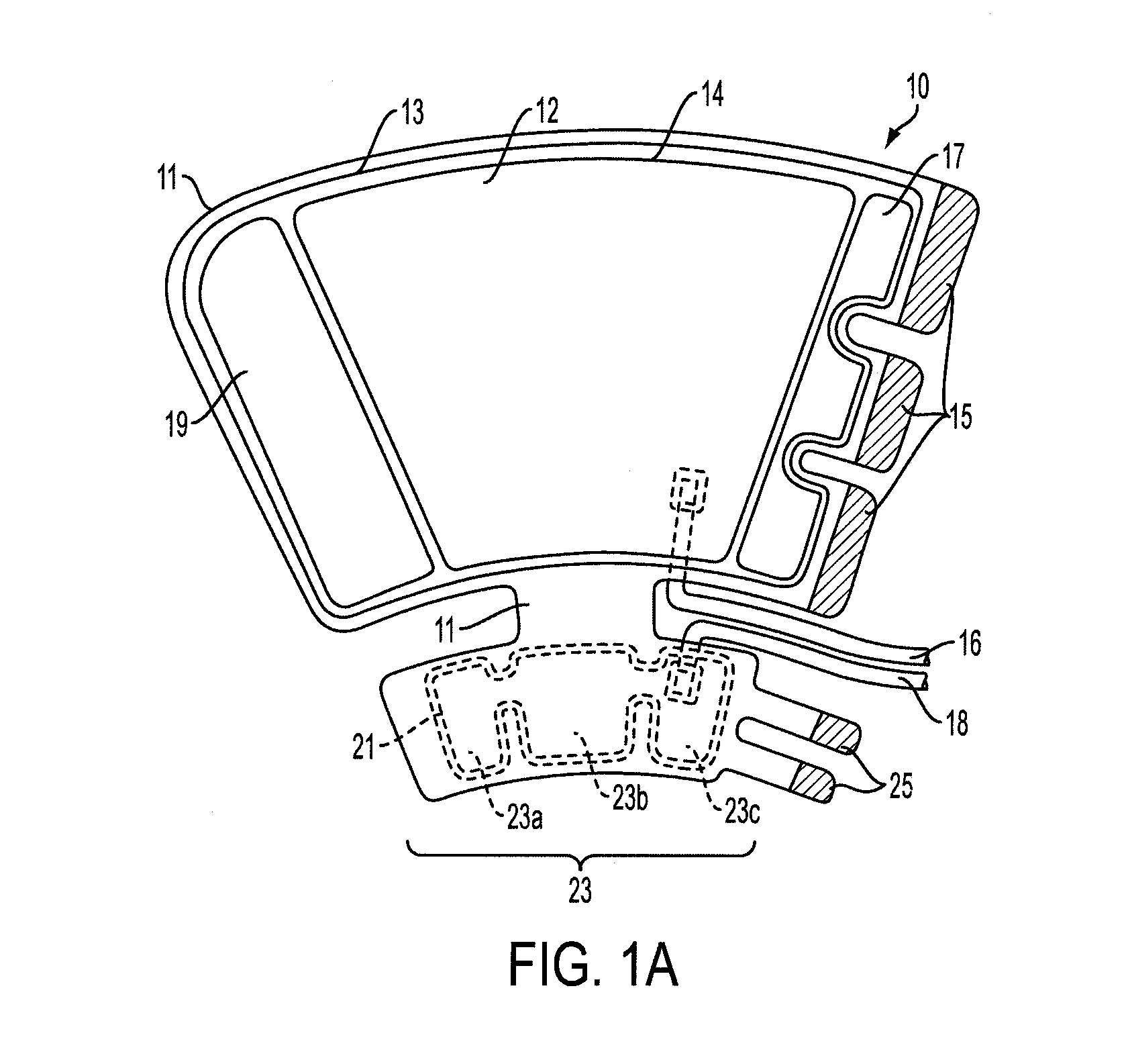
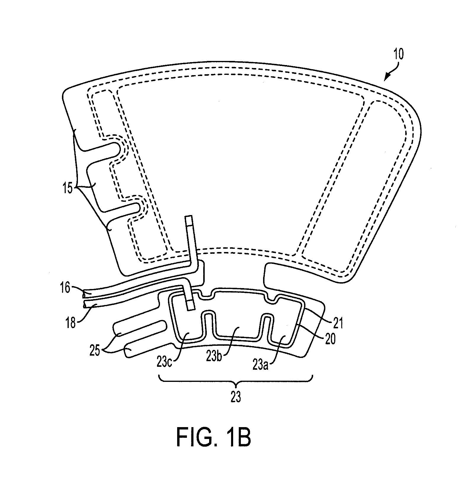
[0046]Reference will now be made to the drawings wherein like reference numerals identify similar structural features or aspects of the subject invention. For purposes of explanation and illustration, and not limitation, a partial view of an exemplary embodiment of the compression garment with heel elevation in accordance with the invention is shown in FIGS. 1A and 1B and is designated generally by reference character 10. Other embodiments of compression garments with heel elevation in accordance with the invention, or aspects thereof, are provided in FIGS. 2-22, as will be described.

[0047]The system of the invention can be used for attachment to the leg and / or foot to provide for compression therapy while also reducing or eliminating pressure on the heel region of the foot when the leg or foot is positioned such that the heel is in contact with an underlying surface (e.g., a bed) or would be in contact with an underlying surface but for the presence of the device. While embodiments...


PUM


Abstract

A compression garment includes a backing member with a proximal end portion and opposed distal end portion. The backing member is configured to be disposed about at least a portion of a lower leg between calf and heel and has an inner surface to be disposed facing the lower leg, and an opposite outer surface. The garment further includes at least one compression bladder disposed within the backing member configured to compress at least a portion of the lower leg to augment venous return flow in the lower leg, an elevation member operatively coupled to the backing member and configured to elevate the heel from an underlying support surface and at least one support member disposed along a portion of the elevation member and along a portion of the backing member to retain the elevation member in a desired position with respect to the backing member to elevate the heel.

Description

CROSS-REFERENCE TO RELATED APPLICATIONS[0001]This application is a continuation-in-part of co-pending application Ser. No. 11 / 494,720, filed Jul. 27, 2006, and is also a continuation-in-part of co-pending application Ser. No. 11 / 356,692, filed Feb. 17, 2006. application Ser. No. 11 / 494,720 is a continuation-in-part of co-pending application Ser. No. 11 / 356,692, each of which claims the benefit of provisional Application No. 60 / 730,766, filed Oct. 27, 2005. Each of these applications is incorporated by reference herein in its entirety.BACKGROUND OF THE INVENTION[0002]1. Field of the Invention[0003]The present invention relates generally to compression systems for vascular therapy. More particularly, the present invention is directed to a compression garment that stimulates or assists venous and / or arterial blood flow and also prevents, treats, and / or relieves decubitus ulcers.[0004]2. Description of Related Art[0005]Various conventional compression devices are known for applying inte...

Claims


Application Information

Patent Timeline
Patent Type & Authority Applications(United States)
IPC IPC(8): A61H7/00
CPCA61F5/012A61F13/069A61G7/0755A61G15/12A61G13/1245A61G13/125A61G13/1265A61G13/12
Inventor RAVIKUMAR, SUNDARAMOSBORNE, GUYRAVIKUMAR, VIKRAMNOLAN, TIMOTHY J.
Owner SUN SCI
Learn More