Fire alarm system transmitter

a transmitter and fire alarm technology, applied in the direction of electrical apparatus, casings/cabinets/drawers, electrical apparatus, etc., can solve the problems of increasing the resin (material) amount of the casing, affecting the insulation property, and difficulty in arranging into the mounting box operation, etc., to achieve sufficient external creepage distance

Inactive Publication Date: 2011-04-21
NOHMI BOSAI LTD
View PDF20 Cites 6 Cited by
  • Summary
  • Abstract
  • Description
  • Claims
  • Application Information

AI Technical Summary

Benefits of technology

[0009]The fire alarm system transmitter according to the present invention includes the electric-wire insertion portion extended toward the outside of the casing from the side wall of the casing facing the one side at which the terminal block of the printed c

Problems solved by technology

However, a creepage distance (clearance) from the terminal block to the insertion hole as an outside of the casing is set to be short, and hence the insulating property may be adv

Method used


Image

  • Fire alarm system transmitter
  • Fire alarm system transmitter
  • Fire alarm system transmitter

Examples


Embodiment Construction

[0018]Hereinafter, a preferred embodiment of a fire alarm system transmitter according to the present invention is described with reference to the drawings.

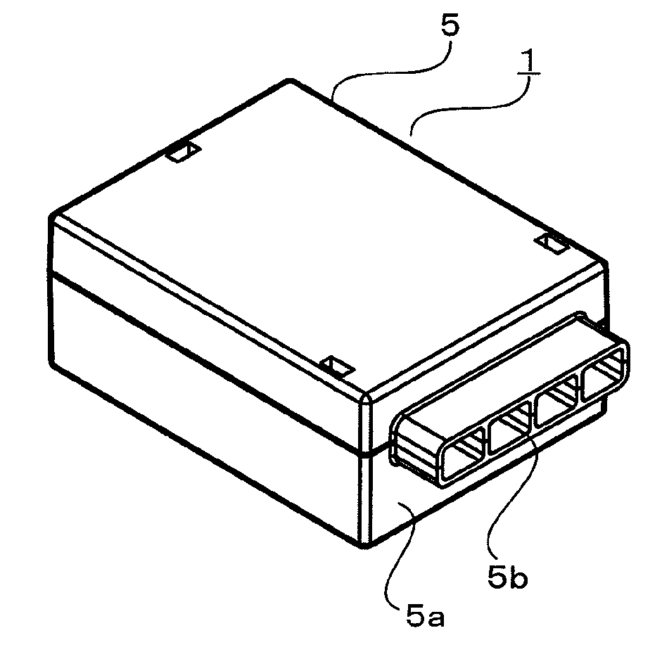
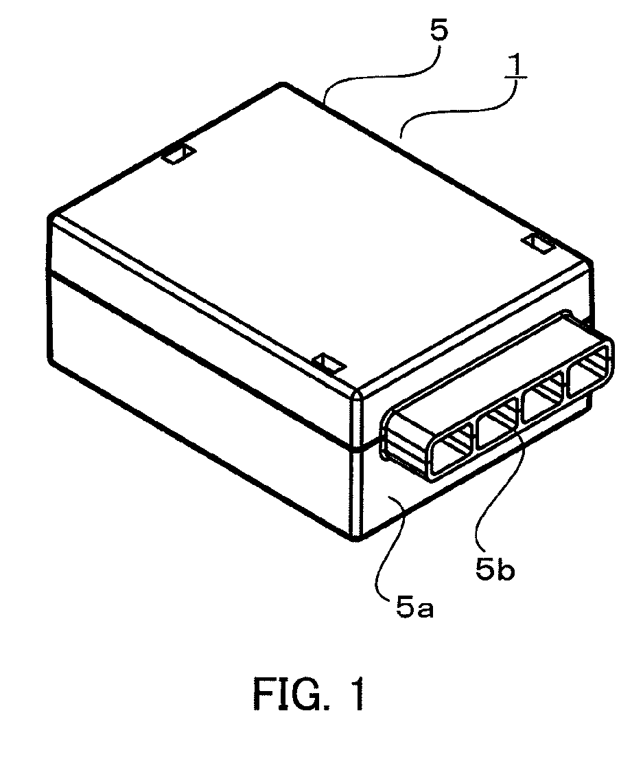
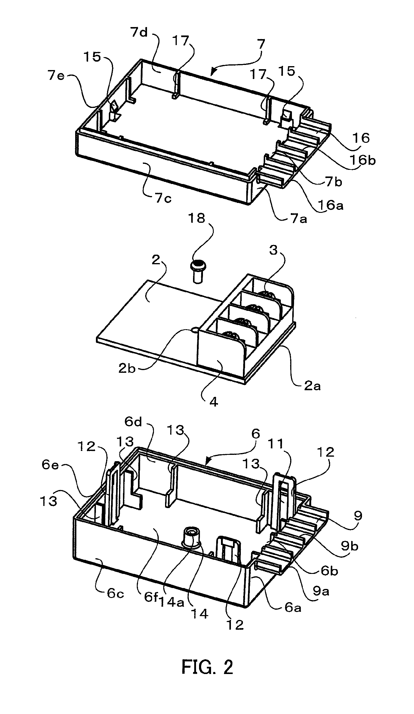
[0019]FIG. 1 is a perspective view of the fire alarm system transmitter according to the embodiment of the present invention. FIG. 2 is an exploded perspective view of the fire alarm system transmitter according to the embodiment of the present invention. FIGS. 3A to 3C are respectively a front view, a plan view, and a side view of the fire alarm system transmitter according to the embodiment of the present invention. FIG. 4 is a sectional view of the fire alarm system transmitter taken along the line A-A of FIG. 3A.

[0020]A fire alarm system transmitter 1 according to the embodiment of the present invention (hereinafter, abbreviated to transmitter 1) relays a signal between a receiver and a detector, for example. The transmitter 1 includes a printed circuit board 2 with a substantially rectangular shape, on which a terminal block...


PUM


Abstract

Obtained is a fire alarm system transmitter having an improved insulating property without increasing an entire size of a casing. The fire alarm system transmitter includes: a printed circuit board with a substantially rectangular shape, on which a terminal block including a plurality of terminals aligned along one side of the printed circuit board is disposed; a casing with a substantially rectangular parallelepiped shape, in which the printed circuit board is mounted; and an electric-wire insertion portion provided on a side wall of the casing facing the one side, and extended from the side wall by a predetermined distance toward an outside of the casing, the side wall allowing a plurality of electric wires connected to the plurality of terminals to be inserted through the side wall.

Description

BACKGROUND OF THE INVENTION[0001]1. Field of the Invention[0002]The present invention relates to a fire alarm system transmitter for use in a fire alarm system.[0003]2. Description of the Related Art[0004]In a transmitter for use in a fire alarm system, a printed circuit board on which a terminal block is fixed is housed inside the transmitter. In an operation of mounting the transmitter to a mounting box, an electric wire extended to an inside of the mounting box is connected to the terminal block, and then, the transmitter is arranged in the mounting box. Finally, a front opening of the mounting box is covered with a plate serving as a decorated frame. Thus, the operation is completed.[0005]Here, in the printed circuit board, in order that a circuit component is not limited in terms of mounting and a mounting area is maximized, the terminal block is disposed along one side of the printed circuit board. At this time, in consideration of an insulating property for the purpose of pre...

Claims


Application Information

Patent Timeline
IPC IPC(8): H05K5/00
CPCH05K5/0247
Inventor MIZUKAMI, AKIRA
Owner NOHMI BOSAI LTD
Why Eureka
Try Eureka