Pivot mount assembly

a mounting assembly and pivoting technology, applied in the field of pivoting/rotating mounting assemblies, can solve the problems of not being able to simply secure to the steering control (i.e., the yoke) of an airplane, unable to read the same and maintain the proper operation of vehicles and respective operating systems, and the current mounting capabilities of the efb do not allow for the same rotation

Inactive Publication Date: 2011-05-05
HECKMAN TOM
View PDF5 Cites 40 Cited by
  • Summary
  • Abstract
  • Description
  • Claims
  • Application Information

AI Technical Summary

Benefits of technology

[0010]This and other aspects are achieved in accordance with the present invention, wherein an aircraft tablet mount assembly for mounting a tablet computer to the steering control of an aircraft is shown having a receiving piece configured to receive an electronic device and having one or more tension elements configured to secure the electronic device and a pivot mount assembly configured to mount the tablet mount assembly to the steering control of the aircraft, comprising. The pivot mount assembly includes an upper portion hav

Problems solved by technology

To date the use of maps and other navigation documents in an aviation or boating environment results in difficulties to read the same and simultaneously maintain proper operation of vehicles and respective operating systems.
The EFB device is bulky and very heavy, and cannot be simply secured to the steering controls (i.e., yo

Method used


Image

  • Pivot mount assembly
  • Pivot mount assembly
  • Pivot mount assembly

Examples


Embodiment Construction

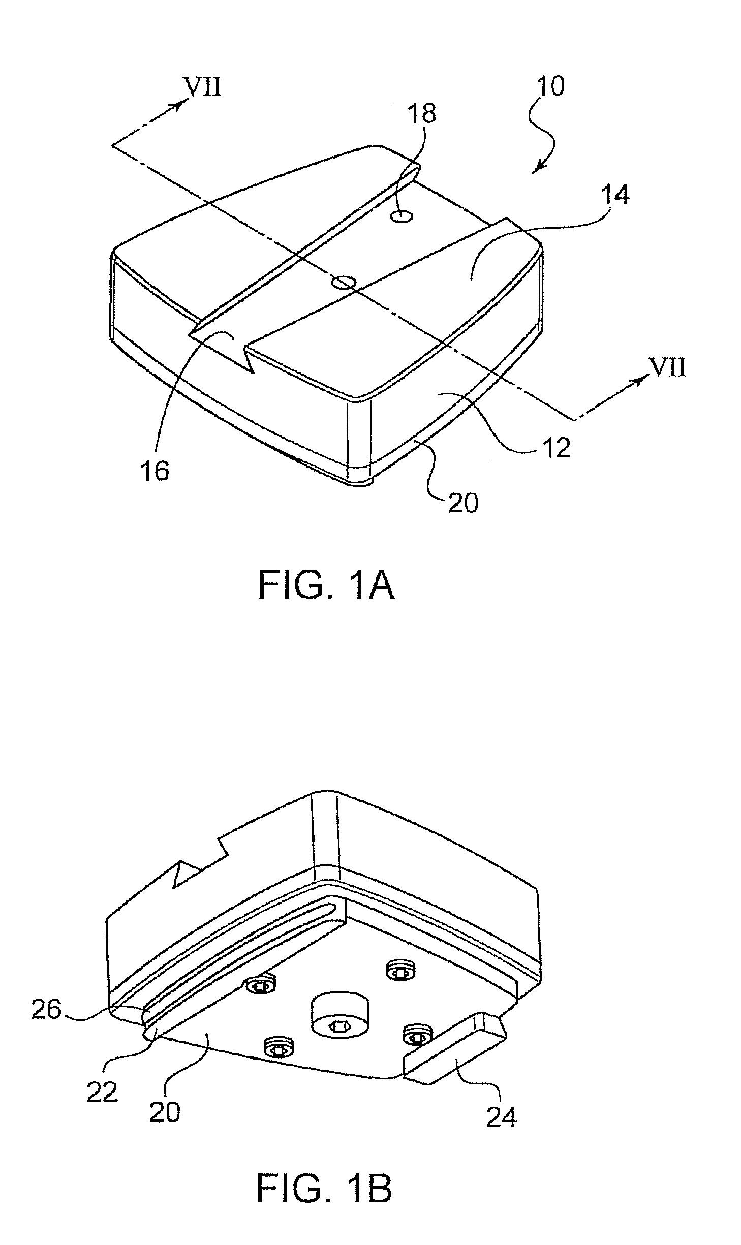
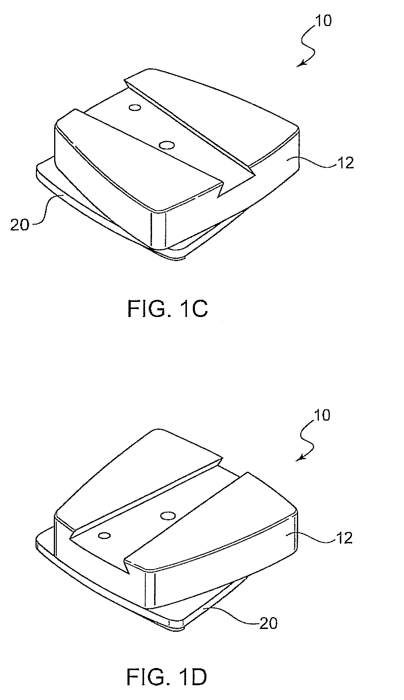
[0037]Referring to FIGS. 1a and 1b, there is shown the pivot mount assembly 10 according to a preferred implementation of the invention. Pivot mount assembly 10 is preferably made up of an upper portion 12 and a lower portion 20. The upper portion 12 includes and upper surface 14 having a receiver / mounting slot 16 for receiving a device to be pivotally mounted. Within the receiver / mounting slot 16 is one or more holes or indents 18 which assist in the securing of the device to be pivotally mounted. In this respect, the device to be mounted would preferably include a locking mechanism that would engage the one or more holes 18 in the slot 16. Alternatively, the device to be mounted can include the holes and the holes 18 in slot 16 would be replaced with a mechanism that engages the holes in the device to secure the same therein.

[0038]According to the preferred implementation, the lower portion 20 includes a position flange 24 and a locking flange 22 having a locking groove 26.

[0039]F...


PUM


Abstract

A tablet mount assembly for mounting an electronic device (e.g., an Apple® iPad®) in the cockpit of an aircraft, and more specifically on the steering control of the aircraft. The tablet mount includes a receiving piece and a pivot mount assembly that includes an upper portion and a lower portion. The upper portion is rotatable with respect to the lower portion. The upper portion includes a slot for connecting to the receiving piece, and the lower portion includes a securing mechanism and a positioning flange. The upper portion of the assembly is rotatable with respect to the lower portion, thereby allowing the electronic device to be mounted to be rotated from a portrait to a landscape orientation without removing the same from the mount. An indexing position system may be integrated between the lower and upper portions of the mount assembly and provides predetermined rotation increments for the device.

Description

CROSS REFERENCE TO RELATED APPLICATIONS[0001]This application is a Continuation-in-Part of co-pending U.S. patent application Ser. No. 12 / 473,787 filed on May 8, 2009, the entire contents of which is incorporated herein by reference.BACKGROUND[0002]1. Technical Field[0003]The present invention relates to mounting assemblies. More particularly, it relates to a pivotable / rotatable mounting assembly for mounting an electronic device within the cockpit of an aircraft, and more specifically to the steering control (yoke) of an aircraft.[0004]2. Description of Related Art[0005]To date the use of maps and other navigation documents in an aviation or boating environment results in difficulties to read the same and simultaneously maintain proper operation of vehicles and respective operating systems. Currently there are systems in place that are essentially clip boards mounted to the steering wheels or other operation controls in an effort to hold the navigation documents in front of the ope...

Claims


Application Information

Patent Timeline
IPC IPC(8): B60R11/00
CPCB64D2045/0075B64D45/00
Inventor HECKMAN, TOM
Owner HECKMAN TOM
Why Eureka
Try Eureka