Satellite position and heading sensor for vehicle steering control

a satellite position and steering control technology, applied in the direction of process and machine control, instruments, navigation instruments, etc., can solve the problems of not taking into account the actual curvature of the terrain, the inability to determine the poi, and the inability to accurately measure the poi. achieve the effect of avoiding the crossing of the desired track

Active Publication Date: 2008-07-15
AGJUNCTION INC
View PDF39 Cites 90 Cited by
  • Summary
  • Abstract
  • Description
  • Claims
  • Application Information

AI Technical Summary

Benefits of technology

[0009]Further disclosed herein in yet another exemplary embodiment is a method of controlling a vehicle comprising: computing a position and a heading for the vehicle; computing a steering control command; based on a proportionality factor multiplied by a difference in a desired position versus an actual position, plus a second proportionality factor multiplied by a difference in a desired heading versus an actual heading, the second proportionality factor ensuring that when the vehicle attains the desired position the vehicle is also directed to the desire

Problems solved by technology

However, in existing satellite positioning systems (SATPS) for guided parallel swathing for precision farming, mining, and the like, the actual curvature of terrain may not be taken into account.
This results in a less than precise production because of the less than precise parallel swathing.
However, if the tractor is on an inclined terrain with a variable tilt, which is often the case, the SATPS alone cannot determine the terrain tilt so the POI also cannot be determined.
This results in a guidance error because the POI is approximated by the point of reception (POR), and this approximation worsens as the terrain inclination increases.
This results in cross track position excursions relative to the vehicle ground track which would contaminate any attempt to parallel a defined field line or swath.
Systems using Doppler radar will encounter errors with th

Method used


Image

  • Satellite position and heading sensor for vehicle steering control
  • Satellite position and heading sensor for vehicle steering control
  • Satellite position and heading sensor for vehicle steering control

Examples


Embodiment Construction

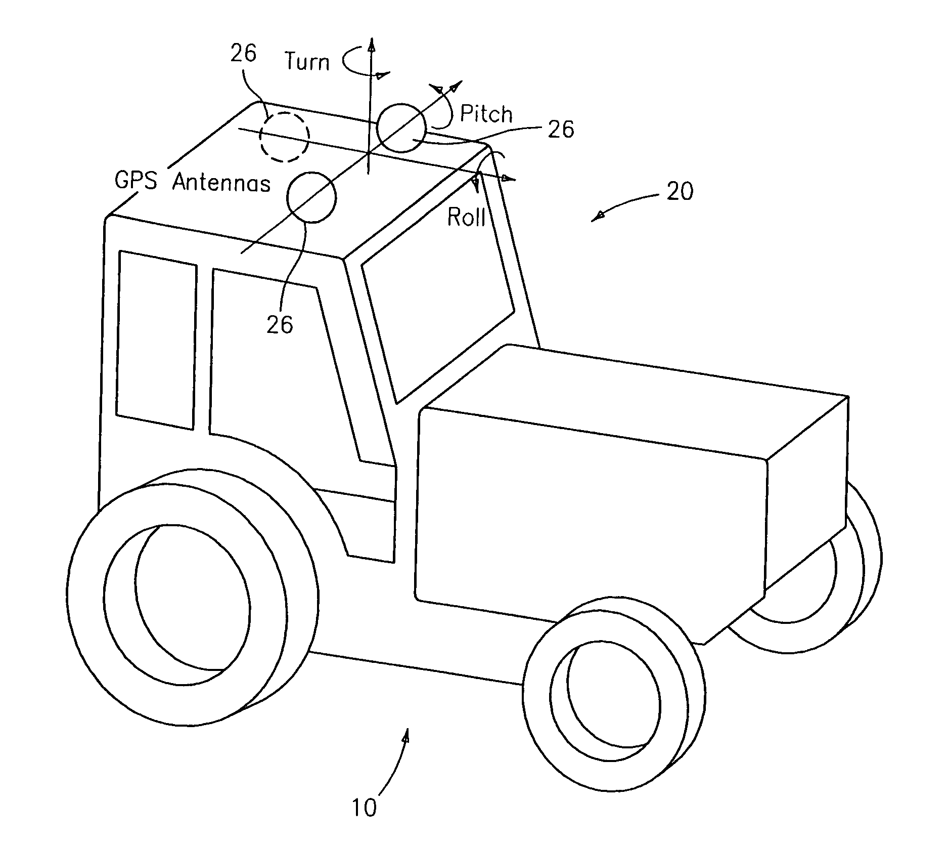
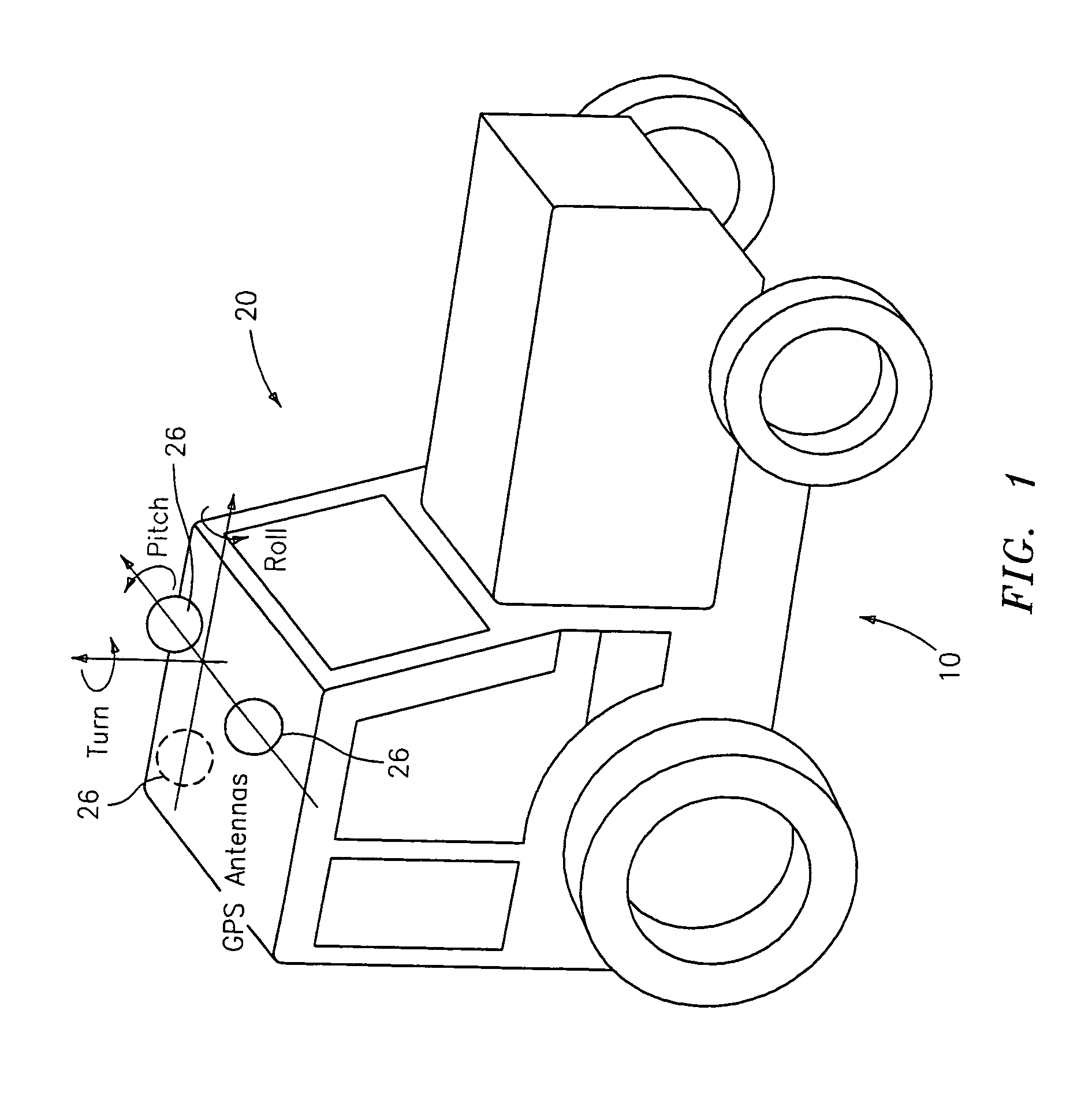
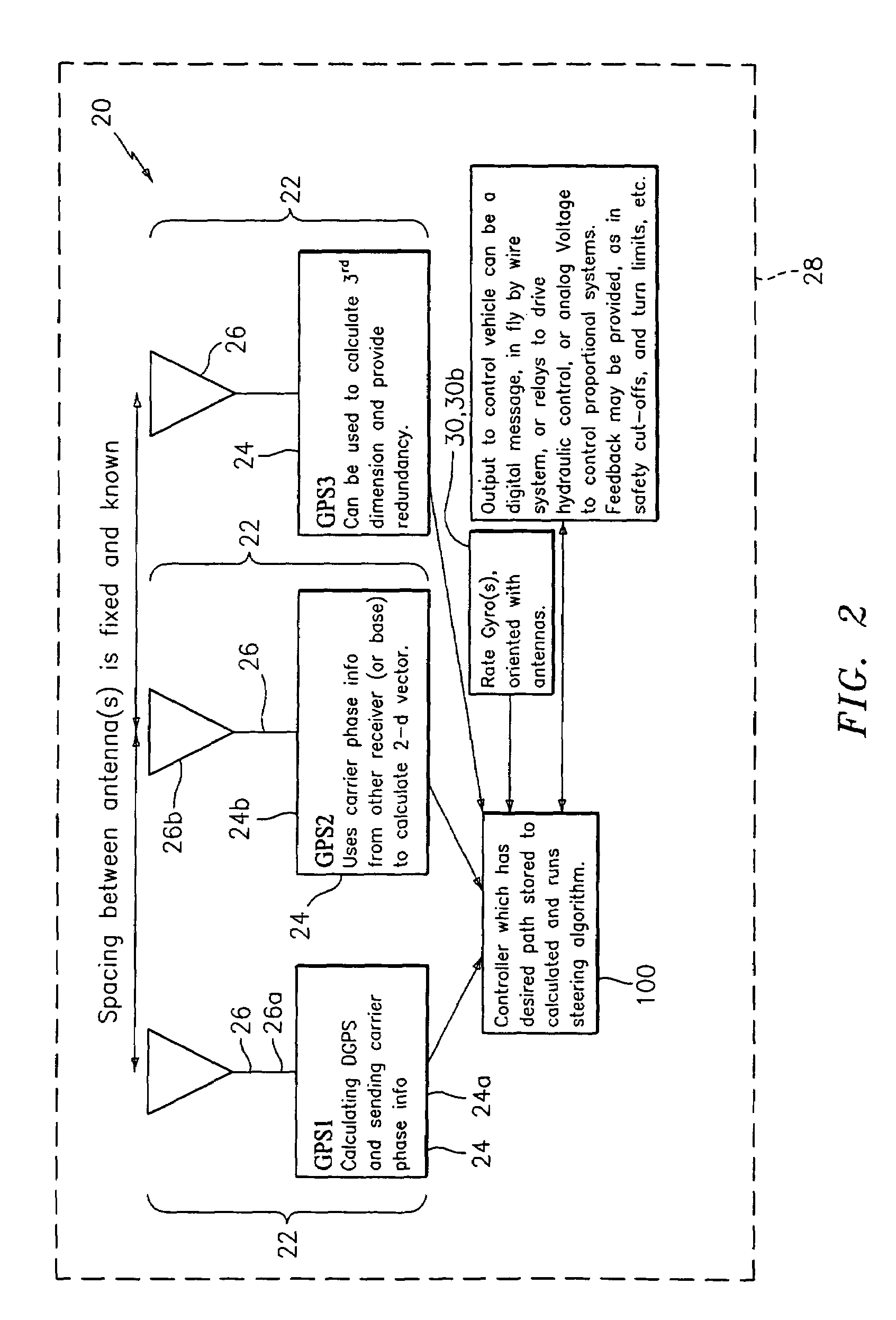
[0017]Disclosed herein in an exemplary embodiment is a sensor system for vehicle guidance. The sensor system utilizes a plurality of GPS carrier phase differenced antennas to derive attitude information. Moreover, the GPS position may optionally be combined with one or more rate gyro(s) used to measure turn rates. In an exemplary embodiment, the rate gyros and GPS receiver / antenna are integrated together within the same unit, to provide multiple mechanisms to characterize a vehicles motion and position to make a robust vehicle steering control mechanism.

[0018]It is known in the art that by using GPS satellite's carrier phase, and possibly carrier phases from other satellites such as WAAS satellites, a position may readily be determined to within millimeters. When accomplished with two antennas at a fixed spacing, an angular rotation may be computed using the position differences. In an exemplary embodiment, two antennas placed in the horizontal plane may be employed to compute a hea...


PUM


Abstract

A sensor system for vehicle steering control comprising: a plurality of global navigation satellite sensor systems (GNSS) including receivers and antennas at a fixed spacing to determine a vehicle position, velocity and at least one of a heading angle, a pitch angle and a roll angle based on carrier phase corrected real time kinematic (RTK) position differences. The roll angle facilitates correction of the lateral motion induced position errors resultant from motion of the antennae as the vehicle moves based on an offset to ground and the roll angle. The system also includes a control system configured to receive the vehicle position, heading, and at least one of roll and pitch, and configured to generate a steering command to a vehicle steering system.

Description

CROSS-REFERENCE TO RELATED APPLICATIONS[0001]This application claims the benefit of U.S. Provisional Application No. 60 / 456,146, filed Mar. 20, 2003 the contents of which are incorporated by reference herein in their entirety.BACKGROUND[0002]The invention relates generally to automatic guidance systems and more specifically to global positioning system based sensor for vehicle steering control.[0003]Movable machinery such as agricultural equipment, open-pit mining machines and airplane crop dusters and the like all benefit from accurate global positioning system (GPS) high precision survey products, and others. However, in existing satellite positioning systems (SATPS) for guided parallel swathing for precision farming, mining, and the like, the actual curvature of terrain may not be taken into account. This results in a less than precise production because of the less than precise parallel swathing. Indeed, in order to provide parallel swaths through a field (in farming for example...

Claims


Application Information

Patent Timeline
IPC IPC(8): G01C21/28G01C21/00G05D1/00G01S19/14G01S19/53
CPCA01B69/008G01S19/14G01S19/53G05D1/027G05D1/0278G05D2201/0201
Inventor FELLER, WALTERWHITEHEAD, MICHAEL L.MCCLURE, JOHN A.
Owner AGJUNCTION INC
Why Eureka
Try Eureka