Beam scanning display apparatus

a display apparatus and beam scanning technology, applied in the field of beam scanning display apparatus, can solve the problems of increasing the size of the optical system of the hmd, affecting the image quality and the actual beam waist position may deviate, so as to reduce the size of the optical system and improve the image quality. the effect of the scanning type image display apparatus

Inactive Publication Date: 2011-05-05
PANASONIC CORP
View PDF3 Cites 36 Cited by
  • Summary
  • Abstract
  • Description
  • Claims
  • Application Information

AI Technical Summary

Benefits of technology

[0019]An object of the present invention is to solve the aforesaid problems occurring in a beam scanning display apparatus by disposing means for adjusting a beam waist position between a scanning unit and a deflecting unit, thereby realizing both an improvement in the image quality of a scanning type image display apparatus and a reduction in the size of an optical system.
[0021]According to this constitution, the beam waist position of the scanned beam can be modified to an optimum position using the fixed lens, enabling an improvement in the quality of a displayed image. Further, since the beam waist position is corrected by the fixed lens, there is no need to drive a lens, a mirror, or the like, in contrast to the prior art, and therefore a high-quality image can be displayed to the user while achieving a reduction in the size of an optical system.

Problems solved by technology

However, in a method where the beam waist position of the laser beam is modified at high speed by subjecting a lens or the like to simple harmonic driving, such as the conventional method described above, an actuator or the like for driving the lens is required, leading to an increase in the size of an optical system of the HMD.
In an eyeglass-type HMD, the optical system needs to be small from the viewpoints of wearability and design, and it is therefore difficult to respond to this requirement with a lens driving method.
Further, with a method in which the lens position is modified using an actuator, an actual beam waist position may deviate greatly from an ideal beam waist position when an operation of the scanning unit deviates from an operation of the actuator.
In Patent Document 1 and Patent Document 2, however, the aforesaid problems regarding the size of the optical system for controlling the beam waist position are not taken into consideration.

Method used


Image

  • Beam scanning display apparatus
  • Beam scanning display apparatus
  • Beam scanning display apparatus

Examples


first embodiment

[0046]An embodiment of the present invention will be described below with reference to the drawings. In this embodiment, an eyeglass-type HMD (Head Mounted Display) will be described as an example of a beam scanning display apparatus according to the present invention.

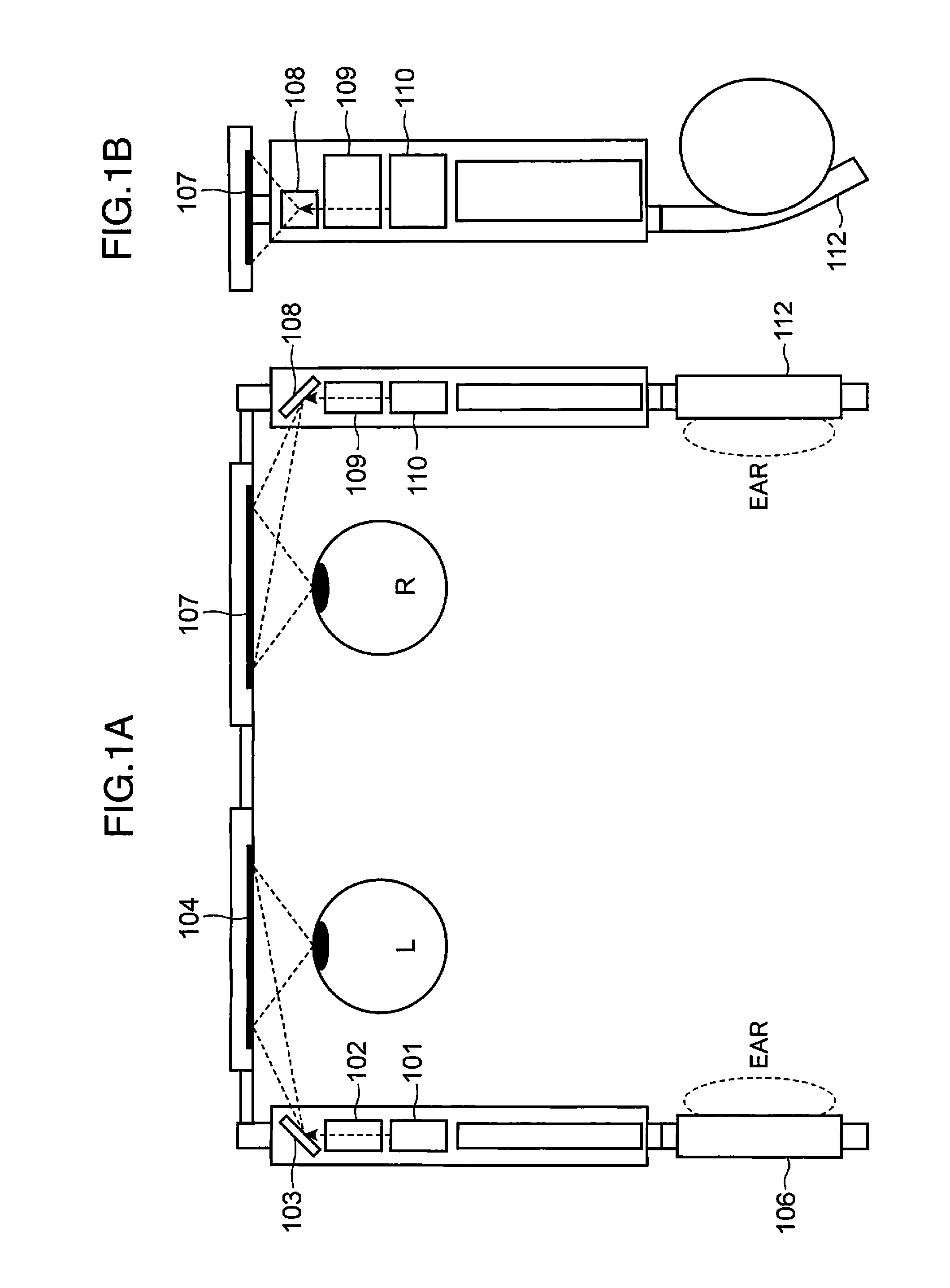
[0047]FIG. 4A is a plan view showing a constitutional example of an eyeglass-type HMD according to the first embodiment. FIG. 4B is a side view of the eyeglass-type HMD shown in FIG. 4A. FIG. 5 is a view showing in detail the constitution of the eyeglass-type HMD shown in FIGS. 4A and 4B.

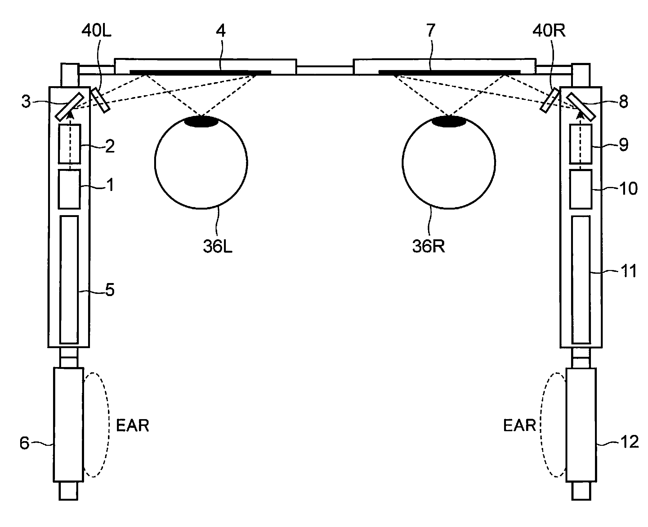
[0048]As shown in FIGS. 4A, 4B and 5, the eyeglass-type HMD according to this embodiment includes laser light sources 1 / 10 (light source units) that are carried on an eyeglass frame to emit laser beams (light beams), wavefront shape modification units 2 / 9 for controlling wavefronts of the laser beams, and scanning units 3 / 8 for scanning the laser beams in a two-dimensional direction.

[0049]As shown in FIG. 5, the laser light source 1 in...

second embodiment

[0104]Another embodiment of the present invention will now be described below with reference to the drawings. Similar constitutional elements to those of the first embodiment have been allocated similar member numbers and description thereof has been omitted where appropriate.

[0105]FIG. 15 is a diagram showing the constitution of an eyeglass-type HMD (Head Mounted Display) according to this embodiment. In the second embodiment, a wavefront shape modification unit 22 includes two movable lenses 22a and 22b driven in accordance with an operation of the scanning unit 3. The movable lenses 22a and 22b of the wavefront shape modification unit 22 can be driven by an MEMS, a mechanical actuator, or similar. In other words, in this embodiment, the correction unit for correcting the beam waist position of the scanned beam is constituted by the fixed lens 40 and the movable lenses 22a and 22b. The fixed lens 40 and the movable lenses 22a and 22b adjust the beam waist position of the laser bea...

third embodiment

[0114]Another embodiment of the present invention will be described below with reference to the drawings.

[0115]FIG. 17 shows the constitution of the principal parts of an eyeglass-type HMD (Head Mounted Display) according to a third embodiment. Similar constitutional elements to those of the embodiments described above have been allocated identical member numbers, and description thereof has been omitted where appropriate.

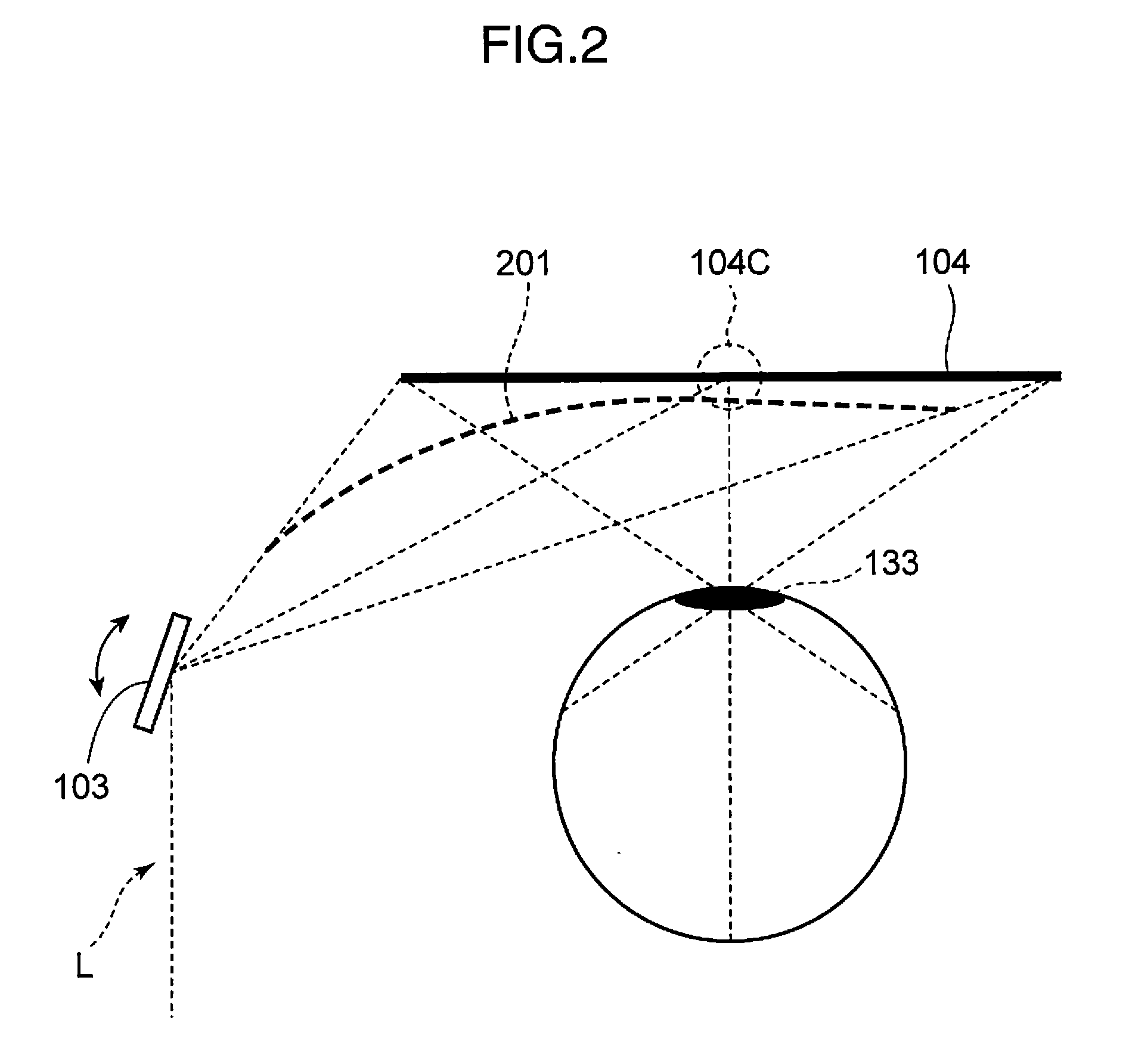
[0116]In this embodiment, the ideal beam waist position of the laser beam L for optimizing the resolution can be modified by forming a deflecting unit 34 attached to an eyeglass lens part in a curved shape. In FIG. 17, a trajectory WOF illustrates the ideal beam waist position when the deflecting unit 34 takes a planar shape, while a trajectory WOC illustrates the ideal beam waist position when the deflecting unit 34 takes a curved shape. In FIG. 17, a trajectory WN illustrates the beam waist position of a laser beam scanned by the scanning unit 3 in a case where t...


PUM


Abstract

A scanning type image display apparatus includes a light source unit for emitting a laser beam, a scanning mirror for scanning the laser beam two-dimensionally in a first direction and a second direction that intersects the first direction, and a control unit for controlling driving of the scanning mirror. The control unit drives the scanning mirror such that a scanning frequency in the first direction is higher than a scanning frequency in the second direction, and varies a scanning amplitude in the first direction by varying the scanning frequency in the first direction in synchronization with a period of the scanning frequency in the second direction.

Description

TECHNICAL FIELD[0001]The present invention relates to a beam scanning display apparatus such as an HMD (Head Mounted Display) or an HUD (Head Up Display).BACKGROUND ART[0002]In a conventional display apparatus such as an HMD (Head Mounted Display), a system (to be referred to hereafter as a beam scanning system) of scanning a laser beam two-dimensionally and drawing the scanned laser beam directly onto a retina of an eye may be employed (see Patent Document 1, for example). A display apparatus used in the beam scanning system is known as a retinal scanning display, a retinal irradiation display, a retina direct drawing display, a beam scanning display, a direct vision display apparatus, an RSD (Retinal Scanning Display), a VRD (Virtual Retinal Display), and so on.[0003]FIGS. 1A and 1B show a constitutional example of an eyeglass-type HMD. As shown in FIGS. 1A and 1B, the eyeglass-type HMD includes laser light sources 101 / 110 carried on an eyeglass frame to emit laser beams, wavefron...

Claims


Application Information

Patent Timeline
Patent Type & Authority Applications(United States)
IPC IPC(8): G02B26/10G02B27/01
CPCG02B26/101G02B2027/0147G02B27/0172G02B26/106
Inventor SUGIYAMA, KEIJIYAMAMOTO, KAKUYAITOH, TATSUOKASAZUMI, KENICHIKUROZUKA, AKIRA
Owner PANASONIC CORP
Why Eureka
Try Eureka