Tunnel multi floor

a tunnel and multi-floor technology, applied in the direction of tunnel lining, shaft lining, underground chambers, etc., can solve the problems of inability to meet the diameter requirements of existing tunnel boring machines, and the problem of also affecting the diameter of existing tunnels

Inactive Publication Date: 2011-05-05
SANTOS SILVINO POMPEU
View PDF6 Cites 5 Cited by
  • Summary
  • Abstract
  • Description
  • Claims
  • Application Information

AI Technical Summary

Benefits of technology

[0009]The slabs have openings, placed close to the circular wall of the tunnel, in one or in both sides of the tunnel, regularly spaced and protected with fireguard devices of box type, which are connected through closed vertical access galleries, to allow for safe passage of people between the roadway galleries and the service gallery.

Problems solved by technology

In current tunnels with more than one lane in each way, the diameter required is unacceptable for the existing tunnel boring machines.
Furthermore, in the case of long tunnels, the existing tunnels are also problematic because it is necessary to built two separated tunnels, one for each way of traffic because of safety reasons.
However, the galleries are much different and it will still be necessary to build a second separated tunnel.

Method used


Image

  • Tunnel multi floor
  • Tunnel multi floor
  • Tunnel multi floor

Examples


Embodiment Construction

)

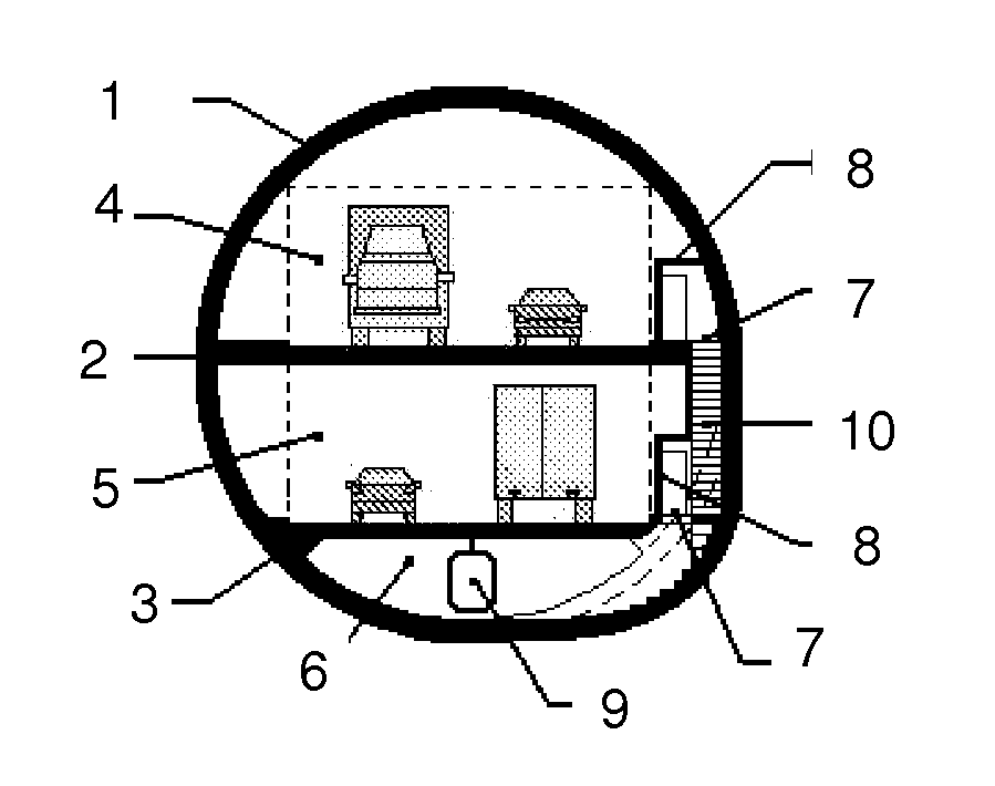
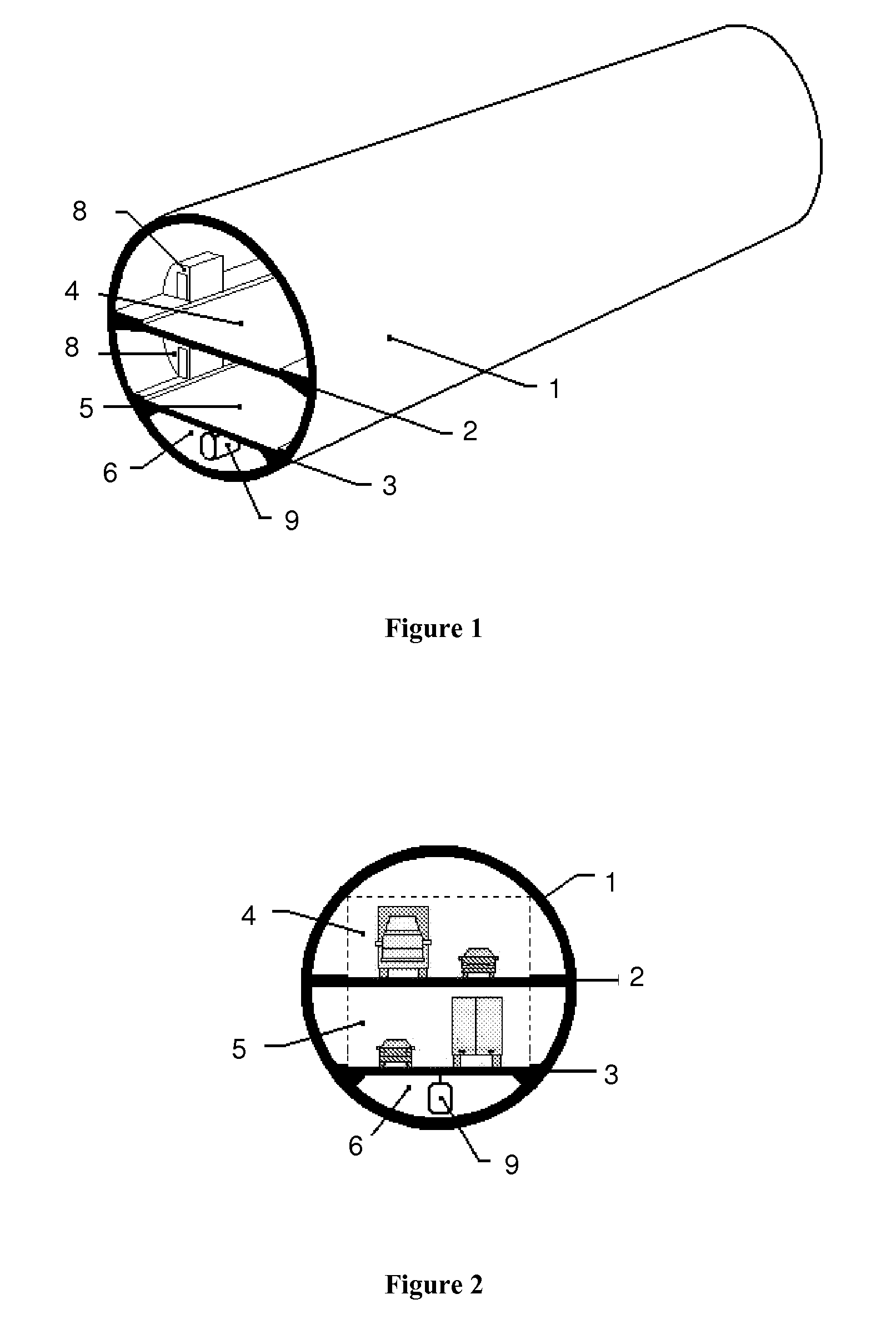
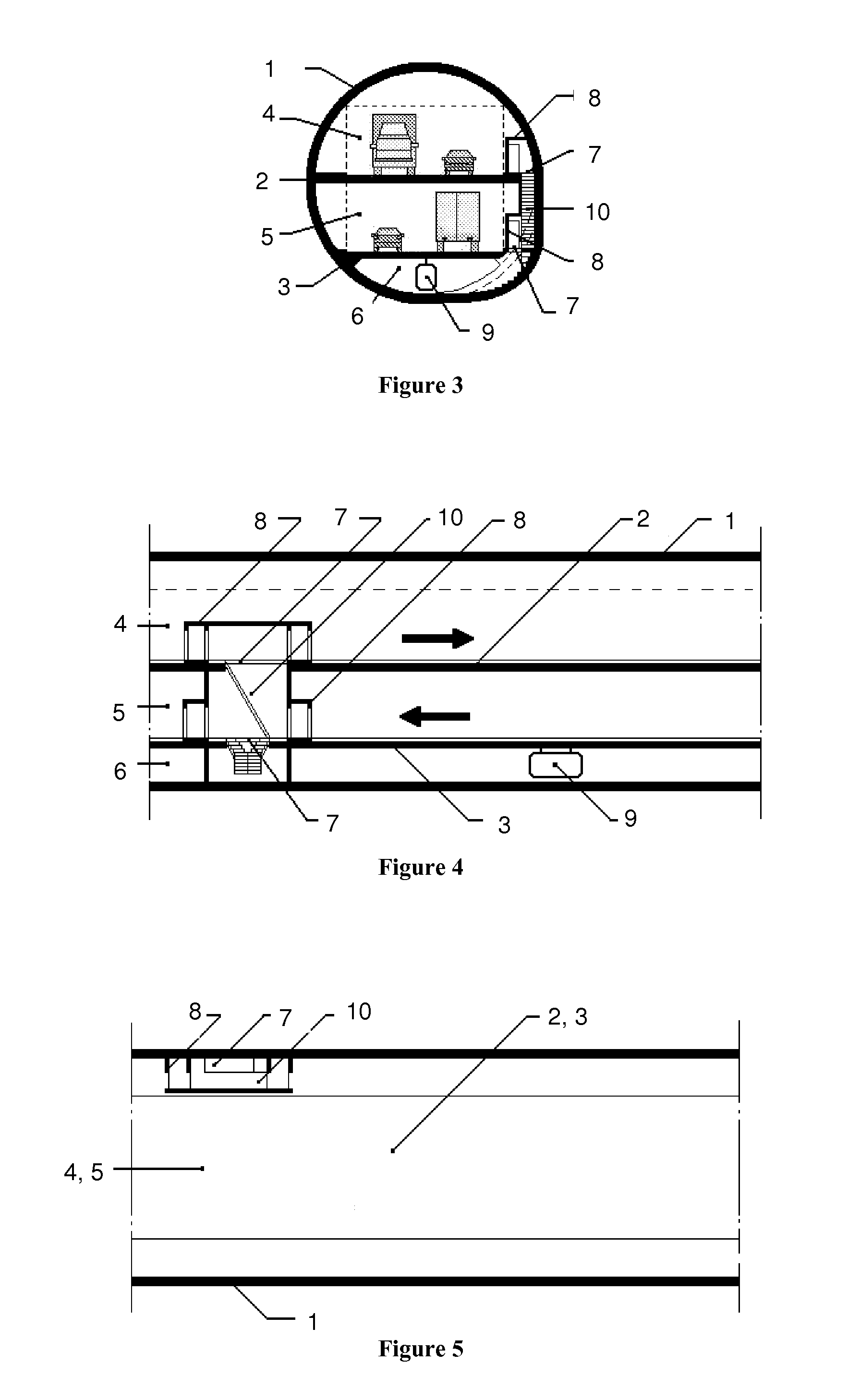
[0016]A tunnel boring machine excavates soil and places precast segments, which are clamped together, in order to form the wall of the tunnel 1, which is circular shaped.

[0017]Referring to FIGS. 1-5, inside of the tunnel 1 two slabs 2, 3 are executed, along the full width of the tunnel, one placed roughly at half the height of the tunnel and the other placed slightly above the bottom of the tunnel. This creates three isolated and independent galleries, one on top of another: two substantially identical roadway galleries 4, 5, one for each way of traffic, and a service gallery 6.

[0018]On the slabs 2 and 3, openings 7 will be arranged, placed close to the circular wall of the tunnel 1, in one or in both sides of the tunnel. The openings will be regularly spaced, protected with fireguard devices 8 of box type, which will be provided with escape doors. The fireguard devices 8 are located on both slabs 2 and 3, and are connected through closed vertical access galleries 10, which are pro...


PUM


Abstract

A multiple floor roadway tunnel has a circular wall and two horizontal slabs, one above the other and spaced apart to create three separate galleries within the tunnel. A service gallery is located between the bottom of the circular wall and the lower horizontal slab. A lower roadway gallery is located between the lower and the upper horizontal slabs. An upper roadway gallery is located between the upper horizontal slab and the top of the circular wall. Openings in the upper and lower slabs are located proximate the circular wall in spaced apart intervals and protected by fire devices of box type, which are connected by closed vertical access galleries for passage of people between galleries. The service gallery has at least one circulating shuttle vehicle, which may suspended from the lower horizontal slab, to allow for local access and the evacuation of people.

Description

BACKGROUND OF THE INVENTION[0001]1. Field of the Invention[0002]The present invention relates to the construction of roadway tunnels of circular cross-section, with two-way traffic, allowing for the creation of two independent and identical roadway galleries, for all kinds of traffic, and a service gallery interconnected with them, in order to provide local access for the personnel and the evacuation of people in case of accident or fire inside the tunnel.[0003]2. Background Art[0004]The construction of roadway tunnels using tunnel boring machines is a solution increasingly used, for both economic and environmental reasons. With this technique, the boring machine excavates soil, and inserts precast segments, in order to form the wall of the tunnel, which becomes circular shaped. Subsequently, a filing on the bottom of the tunnel is executed in order to create a platform for the circulation of vehicles, with the two-way traffic placed side by side.[0005]In current tunnels with more t...

Claims


Application Information

Patent Timeline
Patent Type & Authority Applications(United States)
IPC IPC(8): E21D11/00
CPCE21D9/14
Inventor SANTOS, SILVINO POMPEU
Owner SANTOS SILVINO POMPEU
Why Eureka
Try Eureka