Treatment instrument

Inactive Publication Date: 2011-05-05
OLYMPUS MEDICAL SYST CORP
View PDF0 Cites 31 Cited by
  • Summary
  • Abstract
  • Description
  • Claims
  • Application Information

AI Technical Summary

Benefits of technology

[0029]According to the treatment instrument of the present invention, small-diameter parts are provided at portions of the wires. Consequently, with respect to a bundled part where the wires are bundle

Problems solved by technology

Consequently, there is the problem that it is necessary to configure the inner diameter of the connecting pipe to be at least twice the outer diameter of the wire, and that it is difficul

Method used


Image

  • Treatment instrument
  • Treatment instrument
  • Treatment instrument

Examples


first embodiment

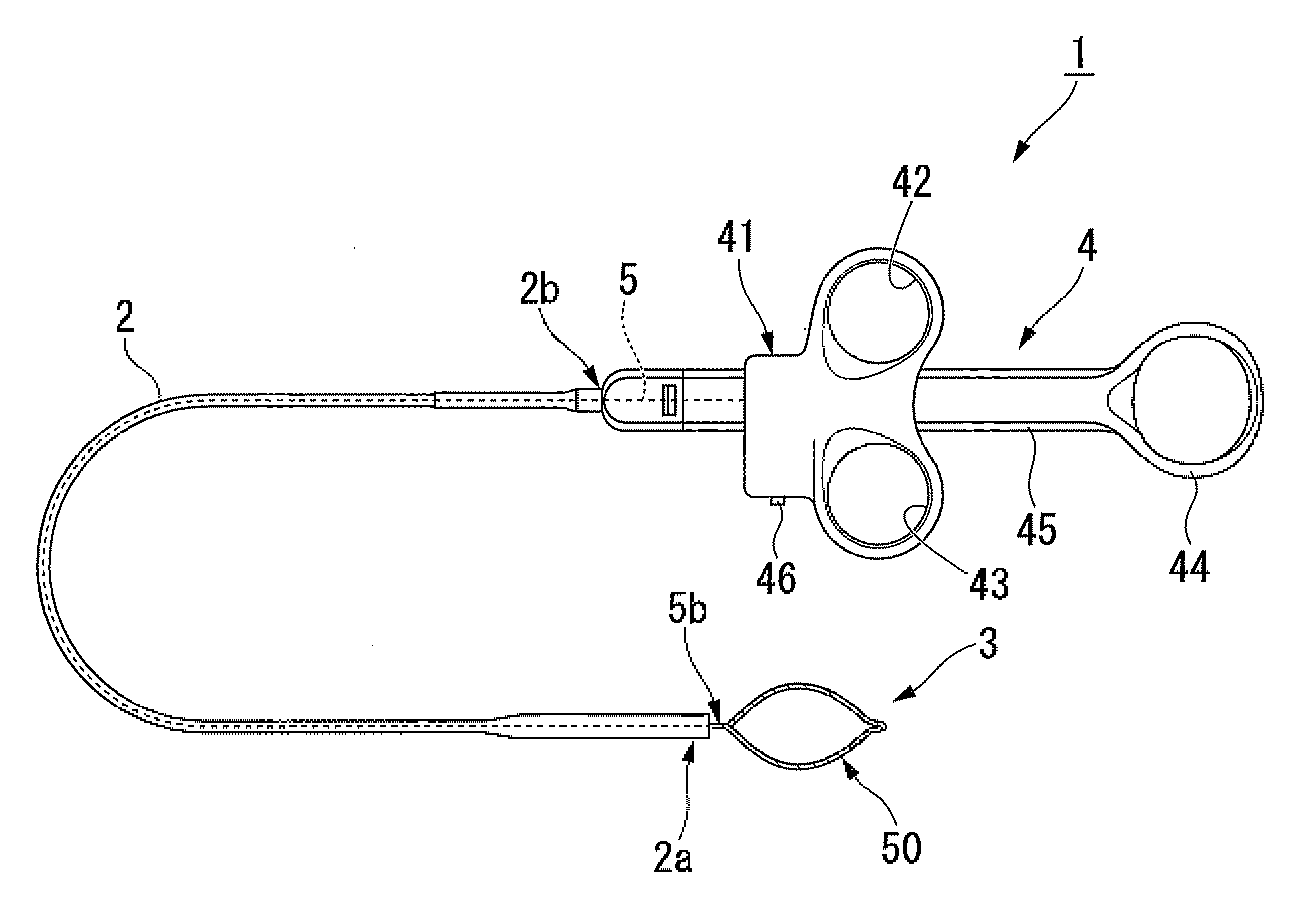
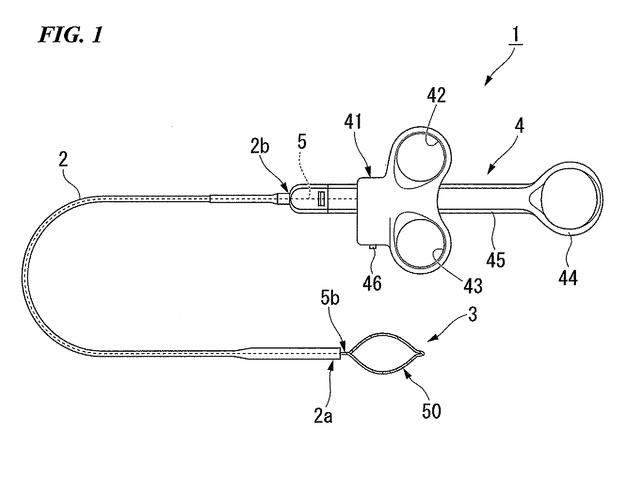
[0052]A treatment instrument of a first embodiment of the present invention is described below with reference to FIG. 1 to FIG. 3.

[0053]FIG. 1 is a plan view which shows a treatment instrument 1 of the present embodiment. As shown in FIG. 1, the treatment instrument 1 is provided with a treatment part 3 that conducts treatment within a body cavity, a manipulation part 4 that is disposed at the side near the operator and that serves to manipulate the treatment part 3, and a tubular sheath 2 that is disposed between the treatment part 3 and the manipulation part 4.

[0054]A manipulation wire 5 that is composed of flexible metallic wire and that is respectively connected to the treatment part 3 and manipulation part 4 runs through the interior of the sheath 2.

[0055]With respect to the manipulation part 4, one may appropriately adopt a configuration of a conventional manipulation part of a treatment instrument. For example, one may adopt a manipulation part provided with a manipulation bo...

second embodiment

[0089]Next, a treatment instrument of a second embodiment of the present invention is described with reference to FIG. 8A to FIG. 8D. In each of the embodiments described below, the same reference symbols are given to items that are common to the configuration of the treatment instrument of the above-described first embodiment, and description thereof is omitted.

[0090]The treatment instrument of the present embodiment is not provided with the manipulation wire 5, and is provided with a wire 450 instead of the wire 50.

[0091]FIG. 8A is a side view of the wire 450. As shown in FIG. 8A, the wire 450 has a first end part 451 and a second end part 452. The first end part 451 is provided with a small-diameter part 451a that is formed like the small-diameter part 251a.

[0092]FIG. 8B is a side view which shows the configuration of the wire 450 after deployment. As shown in FIG. 8B, the wire 450 folds back at an intermediate part 453. Furthermore, a bundled part 455 is formed by welding ancho...

third embodiment

[0095]Next, a treatment instrument of a third embodiment of the present invention is described with reference to FIG. 9A and FIG. 9B. In the present embodiment, wires 550 are multiply provided in which small-diameter parts are formed similar to those of the wire 50 of the first embodiment. For example, FIG. 9B is an enlarged view which shows a partial cross-section in the vicinity of a second bundled part 555. As shown in FIG. 9B, small-diameter parts 551a provided at the end parts of the wires 550 are inserted into and fixed to a connecting tube 554. The small-diameter parts 551a are configured by forming tapered parts at both ends of the wires 550. Although not illustrated in the drawings, end parts of the wires 550 including small-diameter parts are also similarly inserted into and fixed to a first bundled part 6.

[0096]As shown in FIG. 9A and FIG. 9B, in the present embodiment, the wires 550 are bundled in threes to form the first bundled part 6 and second bundled part 555. Accor...


PUM


Abstract

This treatment instrument includes: a flexible wire that has a first end part and a second end part, and that has a treatment part at an intermediate part for conducting treatment within a body cavity; small-diameter parts where at least a portion of the outer circumferential face of the wire has a smaller diameter or is denuded relative to the rest; a bundled part where the wire is bundled so as to at least include the small-diameter parts; and a manipulation wire that is connected to this bundled part.

Description

BACKGROUND OF THE INVENTION[0001]1. Field of the Invention[0002]The present invention relates to a treatment instrument for treating body tissue.[0003]This application claims priority from Japanese Patent Application No. 2009-026583 filed on Feb. 6, 2009, the content of which is incorporated herein by reference.[0004]2. Description of Related Art[0005]Conventionally, as treatment instruments for conducting treatment of body tissue, there are known to be lithotriptic baskets that tightly bind and crush calculi with wire, and high-frequency treatment instruments that grasp body tissue and that perform cautery incisions and the like with wire capable of carrying high-frequency current.[0006]As examples of such treatment instruments, there is, for example, the endoscopic treatment instrument recorded in Patent Document 1 which is provided with a wire capable of carrying high-frequency current. This endoscopic treatment instrument is provided with a manipulation wire that passes through ...

Claims


Application Information

Patent Timeline
IPC IPC(8): A61B18/14A61B17/00A61B17/3205
CPCA61B17/32056A61B18/1492A61B2018/141A61B2018/1407A61B2018/00214
Inventor YANUMA, YUTAKAFUJII, HIDEKI
Owner OLYMPUS MEDICAL SYST CORP
Why Eureka
Try Eureka