Vehicle control device

a technology for controlling devices and vehicles, applied in vehicle position/course/altitude control, process and machine control, instruments, etc., can solve the problems of deteriorating the traveling feeling of the driver of the vehicle, the friction coefficient does not become, etc., and achieves accurate and reliable determination

Inactive Publication Date: 2011-05-05
AISIN AW CO LTD
View PDF6 Cites 12 Cited by
  • Summary
  • Abstract
  • Description
  • Claims
  • Application Information

AI Technical Summary

Benefits of technology

[0023]Accordingly, in the above-described structure, with reference to the predetermined release determining value corresponding to oil pressure at which the release side element no longer has the transfer torque capacity, at least one of detection of decrease of the release side hydraulic instruction value to be equal to or smaller than the release determining value and detection of decrease of the differentia

Problems solved by technology

However, in the engagement element structured generally using a friction member such as a brake and a clutch, the friction coefficient does not become a constant value and may change even in one time of shift operation, due to a rotation speed difference betw

Method used


Image

  • Vehicle control device
  • Vehicle control device
  • Vehicle control device

Examples


Embodiment Construction

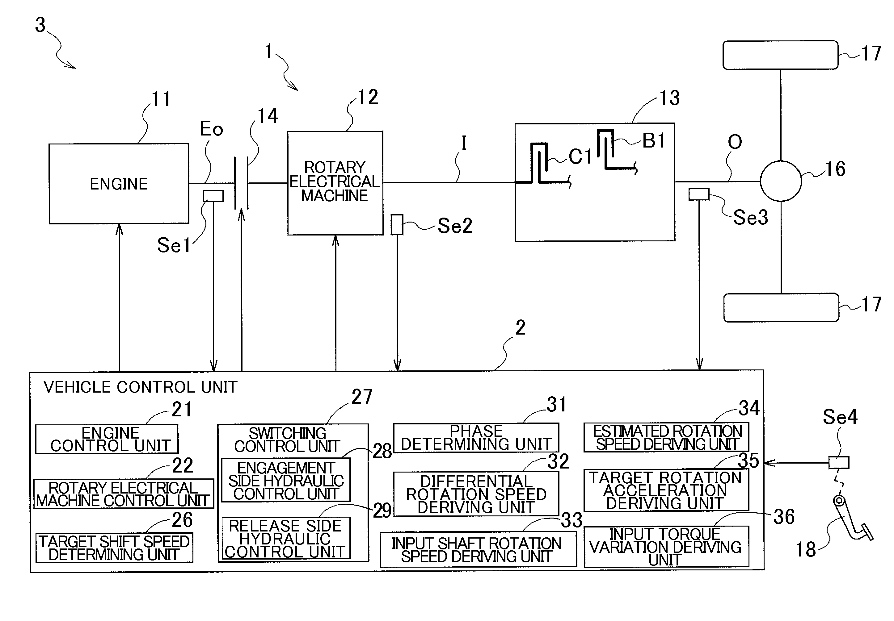
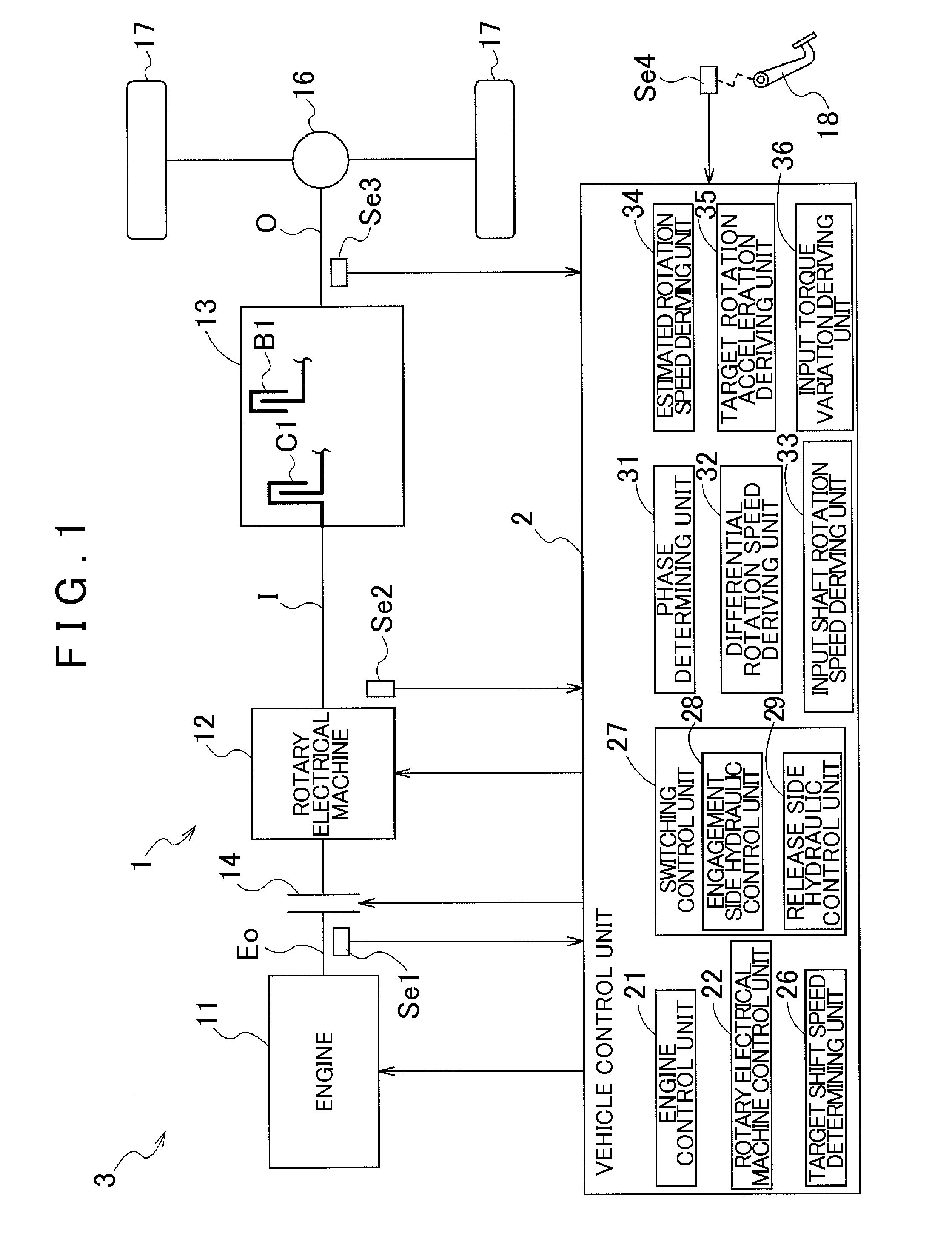
[0030]An embodiment of a vehicle drive apparatus 1 and a vehicle control unit 2 according to the present invention will be described with reference to the drawings. FIG. 1 is a schematic diagram illustrating a general structure of the vehicle drive apparatus 1 according to this embodiment. As illustrated in this diagram, a vehicle 3 having the vehicle drive apparatus 1 is a hybrid vehicle including both an engine 11 and a rotary electrical machine 12 as driving force sources. The vehicle drive apparatus 1 has an input shaft I drive-coupled to the engine 11 and the rotary electrical machine 12 as driving force sources, an output shaft O drive-coupled to wheels 17, and a transmission 13 having a plurality of engagement elements C1, B1 . . . and a plurality of shift speeds in a switchable manner, shifting a rotation speed of the input shaft I with speed ratios of the shift speeds and transmitting the shifted speed to the output shaft O. The vehicle 3 also includes a vehicle control uni...


PUM


Abstract

A vehicle control device for controlling a vehicle drive apparatus, the vehicle control device configured with a phase determining mechanism that determines the end of the torque phase in a shift operation, and a rotary electrical machine control mechanism that controls the torque of the rotary electrical machine using a variation of input torque. The vehicle control device is also configured with an engagement control mechanism that provides feedback controlling supplied oil pressure to an engagement side element as an engagement element on a side to be engaged after switching of shift speeds so that the rotation speed change rate of the input member becomes the target rotation speed change rate.

Description

INCORPORATION BY REFERENCE[0001]The disclosure of Japanese Patent Application No. 2009-251501 filed on Oct. 30, 2009, including the specification, drawings and abstract is incorporated herein by reference in its entirety.BACKGROUND OF THE INVENTION[0002]The present invention relates to a vehicle control device for controlling a vehicle drive apparatus, which includes an input member drive-coupled to a rotary electrical machine as a driving force source, an output member drive-coupled to wheels, and a transmission shifting a rotation speed of the input member with speed ratios of shift speeds and transmitting the shifted speed to the output member.DESCRIPTION OF THE RELATED ART[0003]In late years, electric vehicles having only a rotary electrical machine as a driving force source and hybrid vehicles having both an engine and a rotary electrical machine as driving force sources are in practical use. As an example of a vehicle drive apparatus used for such vehicles, for example, Japane...

Claims


Application Information

Patent Timeline
IPC IPC(8): B60W20/00B60W10/08B60W10/10B60K6/48B60K6/547B60L50/16B60W10/02F16H59/68F16H61/04F16H63/50
CPCB60L2240/423B60W10/08B60W10/115B60W20/00Y02T10/642B60W2710/083F16H61/061F16H63/502F16H2061/0433B60W30/19F16H59/46F16H2059/425Y02T10/64B60W10/02B60W20/40
Inventor TSUDA, KOHEIHAKUMURA, YOMEIASAI, MASAHIROTAJIMA, YOICHIITO, TOMOKAZU
Owner AISIN AW CO LTD
Why Eureka
Try Eureka