Correlation peak location

a peak location and correlation technology, applied in the field of correlation peak location, can solve the problems of noise having a more significant effect on the received signal, noise affecting the chip having a more significant effect,

Inactive Publication Date: 2013-05-14
NXP BV
View PDF5 Cites 0 Cited by
  • Summary
  • Abstract
  • Description
  • Claims
  • Application Information

AI Technical Summary

Benefits of technology

[0008]A peak in the combined samples may incorporate multiple peaks in correlator output samples from respective symbol time periods. Thus, in embodiments of the invention, the peak in the combined samples may be less sensitive to noise and / or is more accurate. Embodiments of the invention may allow the location of the peak in the combined samples to be determined accurately and / or reliably, even in systems that use short pseudonoise (PN) codes to encode the symbols.
[0014]In certain embodiments, the apparatus is arranged to combine the samples by determining a sum of samples from corresponding positions in each of the sample time periods. Thus, there is a simple combining of samples at corresponding positions.

Problems solved by technology

Using shorter PN codes may cause noise to have a more significant effect on a received signal.
For example, a chip in a PN code will constitute a greater proportion of the complete PN code if the PN code is shorter, and therefore noise affecting a chip will have a more significant effect when a shorter PN code is used.

Method used


Image

  • Correlation peak location
  • Correlation peak location
  • Correlation peak location

Examples


Embodiment Construction

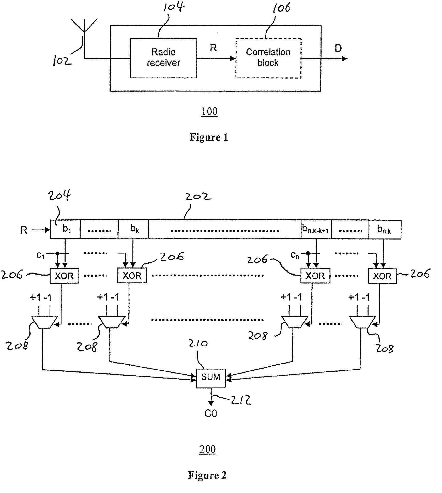
[0034]FIG. 1 shows an example of a DSSS receiver 100 suitable for use in a Direct Sequence Spread Spectrum (DSSS) communication system. The receiver 100 includes an antenna 102 for receiving wireless signals, and a radio receiver 104 for demodulating received signals and producing a demodulated signal R. The demodulated signal R is a digital signal that represents the received signal. Preferably, the sample rate of the received signal is equal to or higher than the chip rate of the chips in the PN codes of the communication system. For example, the sampling rate of the demodulated signal R is 16 times higher than the chip rate of the PN codes.

[0035]The demodulated signal R is then provided to a correlation block 106 which determines the PN codes (if any) within the demodulated signal R and produces a bit stream D of data symbols that were contained within a received signal.

[0036]The correlation block 106 includes a single correlator where a single PN code is used to transmit a binar...


PUM


Abstract

Apparatus for determining a location of a peak in correlation output samples, the apparatus being arranged to receive samples from at least one correlator over a plurality of symbol time periods; combine samples from a period that is longer than the symbol time period into combined samples; and determine the position of a peak in the combined samples.

Description

FIELD OF THE INVENTION[0001]Embodiments of the present invention relate to correlation peak location, for example determining the location of a peak in correlation data from one or more correlators in a wireless receiver or transceiver.BACKGROUND TO THE INVENTION[0002]Direct Sequence Spread Spectrum (DSSS) signals are formed from pseudo-random noise (PN) codes. A PN code is a binary sequence of chips (or bits). The PN code has a higher bit rate than the symbols represented by the PN codes. In some systems, each PN code is used to represent a unique data symbol. In other systems, a single PN code can be used to represent multiple symbols by changing the polarity of the transmitted PN code. DSSS receivers perform a correlation process between a received signal and the PN codes specific to that particular communication system. The magnitude of the correlation result indicates the extent to which the received signal and the symbol PN codes are matched in phase. The correlation process m...

Claims


Application Information

Patent Timeline
Patent Type & Authority Patents(United States)
IPC IPC(8): H04L27/06
CPCH04B1/7077H04B1/7093
Inventor LAWROW, IVAN
Owner NXP BV
Why Eureka
Try Eureka