An apparatus and method for detecting a tool

Active Publication Date: 2020-09-24
KONINKLJIJKE PHILIPS NV
View PDF0 Cites 0 Cited by
  • Summary
  • Abstract
  • Description
  • Claims
  • Application Information

AI Technical Summary

Benefits of technology

[0021]The image processing unit is adapted to process the 3D image obtained by the 3D ultrasound imaging apparatus to determine which plane of the 3D image represents a plane of the 3D volume that includes the entire length of the tool, including a tip of the tool. This plane is called the tool plane section. By performing the first tool detection procedure, the tool plane section is rapidly identified enabling the position and orientation of the tool to be efficiently and reliably determined. By detecting the position of the tool plane section, it is possible to visualize the long-axis view of the tool. In addition, other views of the tool can be determined with respect to the tool plane section. For example, a plane

Problems solved by technology

However, this mode of imaging has a number of drawbacks.
In particular, 2D imaging has a limited field of view; after a successful alignment and localization of the tool in the ultrasound image and while moving the tool or assessing the target, any undesired hand motion of the person conducting the procedure may cause misalignment of the tool and the ultrasound transducer such that parts of the tool are excluded from the ultrasound image.
This may lead to incorrect placement of the tool.
Furthermore, during the procedure, the focus of the operator may be diverted from treatment, as they may be distracted by searching for the tool in the ultrasound image.
External tool tracking systems also have a number of disadvantages, since they require additi

Method used


Image

  • An apparatus and method for detecting a tool
  • An apparatus and method for detecting a tool
  • An apparatus and method for detecting a tool

Examples


Embodiment Construction

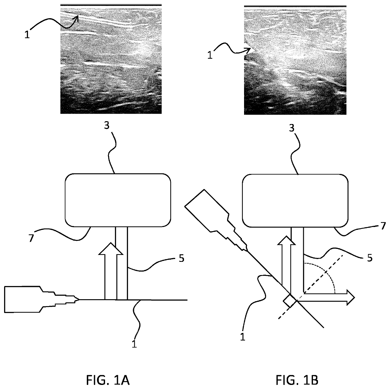
[0074]The invention provides an apparatus for detecting a tool in which a 3D ultrasound image is processed by obtaining a set of planar sections from the 3D ultrasound image. A tool shadow region present in a planar section is identified, and the location of a tool plane section within the 3D ultrasound image is determined. The tool plane section represents a plane within the 3D image in which the entire length of the tool is present, based on the detected tool shadow regions. This then enables the tool to be visualized in the most effective way for the user of the system.

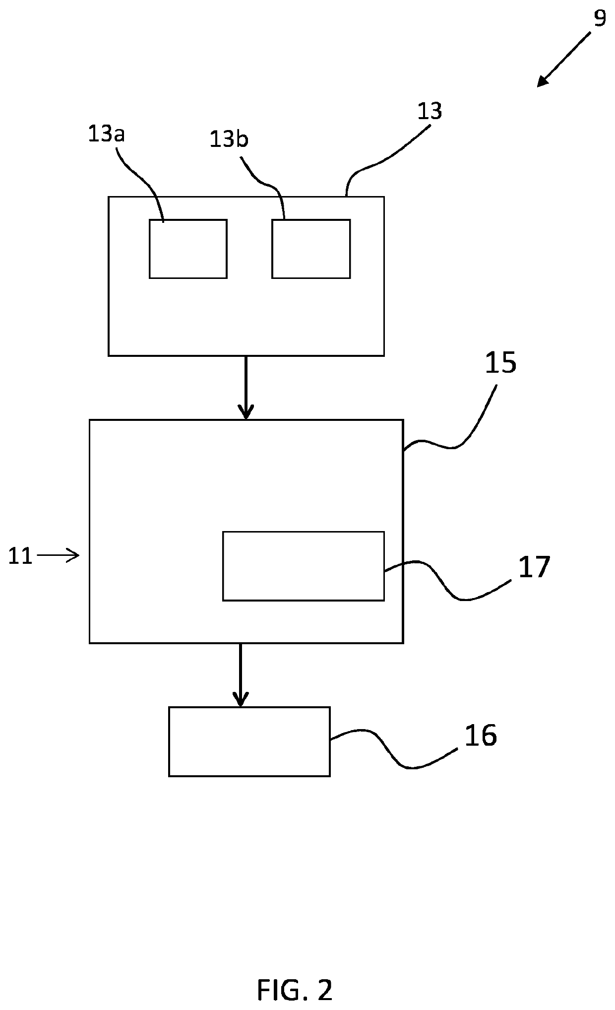
[0075]FIG. 2 is a schematic block diagram illustrating an ultrasound guidance system 9 including an apparatus 11 according to an example. The apparatus 11 is adapted to detect a tool within a 3D image obtained by a 3D ultrasound imaging system 13 comprising an ultrasound emitter 13a and an image sensor 13b. The 3D ultrasound system may comprise an ultrasound probe (not shown). The ultrasound emitter 13a and the ima...


PUM


Abstract

The apparatus is adapted to detect a tool based on a 3D image obtained by a 3D ultrasound imaging system. The apparatus comprises an image processing unit, which includes a tool detection module configured to perform a tool detection procedure. The tool detection procedure involves identifying a shadow of the tool in the 3D image and calculating the position of a “tool plane section” of the 3D image in which the entire length of the tool is represented.

Description

FIELD OF THE INVENTION[0001]The present invention relates to an apparatus and method for detecting a tool, and in particular to an apparatus and method for imaging an interventional tool using images obtained by ultrasound imaging.BACKGROUND OF THE INVENTION[0002]Ultrasound imaging is one of the most popular imaging systems for tool guidance applications. Ultrasound imaging may be used to image tools such as needles, laparoscopes, stents, and radioactive seeds used for brachytherapy. For example, ultrasound imaging may be used for needle guidance in anesthesiology, tissue ablation or for biopsy guidance, since needles are used to take tissue samples, and to deliver medicine or electrical energy to the targeted tissue inside a patient's body. During these procedures, visualization of the needle and its tip is very important in order to minimize risk to the patient and improve health outcomes.[0003]Typically, 2D ultrasound guidance is used to visualize a tool while a procedure is bein...

Claims


Application Information

Patent Timeline
IPC IPC(8): A61B8/08A61B34/20
CPCA61B2034/2063A61B8/0841A61B2090/378A61B8/5207A61B8/523A61B2034/2065A61B8/483A61B34/20
Inventor POURTAHERIAN, ARASHKORSTEN, HENDRIKUS HUBERTUS MARIAMIHAJLOVIC, NENADHUANG, JINFENGDE WITH, PETER HENDRIK NELIS
Owner KONINKLJIJKE PHILIPS NV
Why Eureka
Try Eureka