
A computer-implemented or hardware-implemented method of entity identification, a computer program product and an apparatus for entity identification

a computer program and entity identification technology, applied in the field of computer program products and entity identification apparatuses, can solve the problems of requiring a lot affecting the performance of existing neural network solutions, and requiring a large amount of computer power and/or energy

Active Publication Date: 2022-08-25
INTUICELL AB
View PDF1 Cites 0 Cited by
  • Summary
  • Abstract
  • Description
  • Claims
  • Application Information

AI Technical Summary

Benefits of technology

The present patent proposes a method to identify entities using a network of nodes with input from sensors. The method generates an activity level for each node based on the input from sensors, compares it to a threshold level, and calculates a total activity level as a combination of all activity levels. This process is repeated until a local minimum of the total activity level is reached. When the local minimum is reached, the method utilizes the distribution of activity levels at the local minimum to identify a measurable characteristic of the entity. This method has the advantages of dynamically adapting to changes in input, being less sensitive to noise, and allowing for faster and more accurate identification. Additionally, the method takes into account dependency between sensors, which further improves accuracy.

Problems solved by technology

However, existing neural network solutions have poor performance and / or low reliability.
Furthermore, the existing solutions take a significant time to train and therefore may require a lot of computer power and / or energy, especially for training.
Moreover, existing neural network solutions may require a lot of storage space.

Method used


Image

  • A computer-implemented or hardware-implemented method of entity identification, a computer program product and an apparatus for entity identification
  • A computer-implemented or hardware-implemented method of entity identification, a computer program product and an apparatus for entity identification
  • A computer-implemented or hardware-implemented method of entity identification, a computer program product and an apparatus for entity identification

Examples


Embodiment Construction

[0041]The present disclosure will now be described with reference to the accompanying drawings, in which preferred example embodiments of the disclosure are shown. The disclosure may, however, be embodied in other forms and should not be construed as limited to the herein disclosed embodiments. The disclosed embodiments are provided to fully convey the scope of the disclosure to the skilled person.

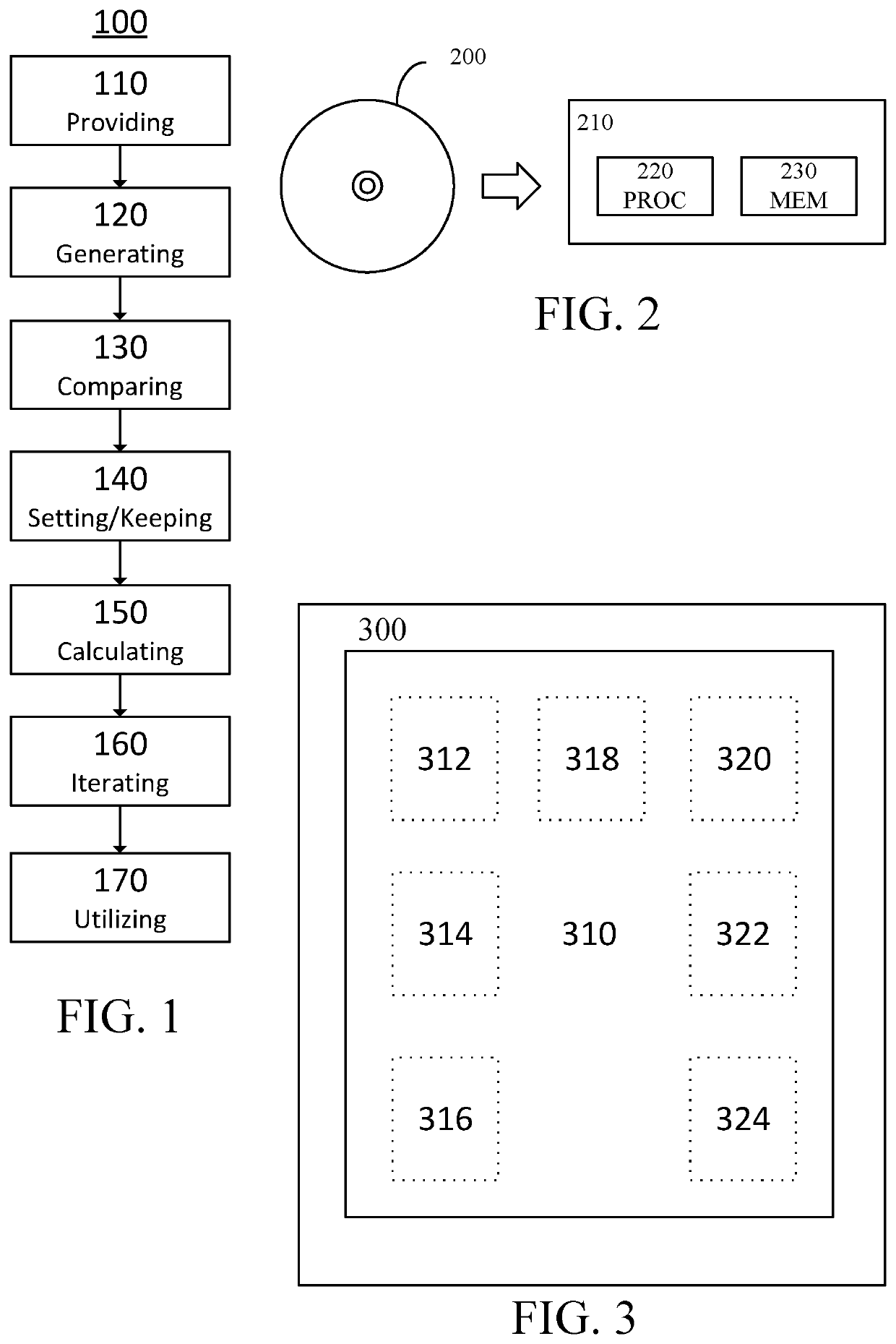
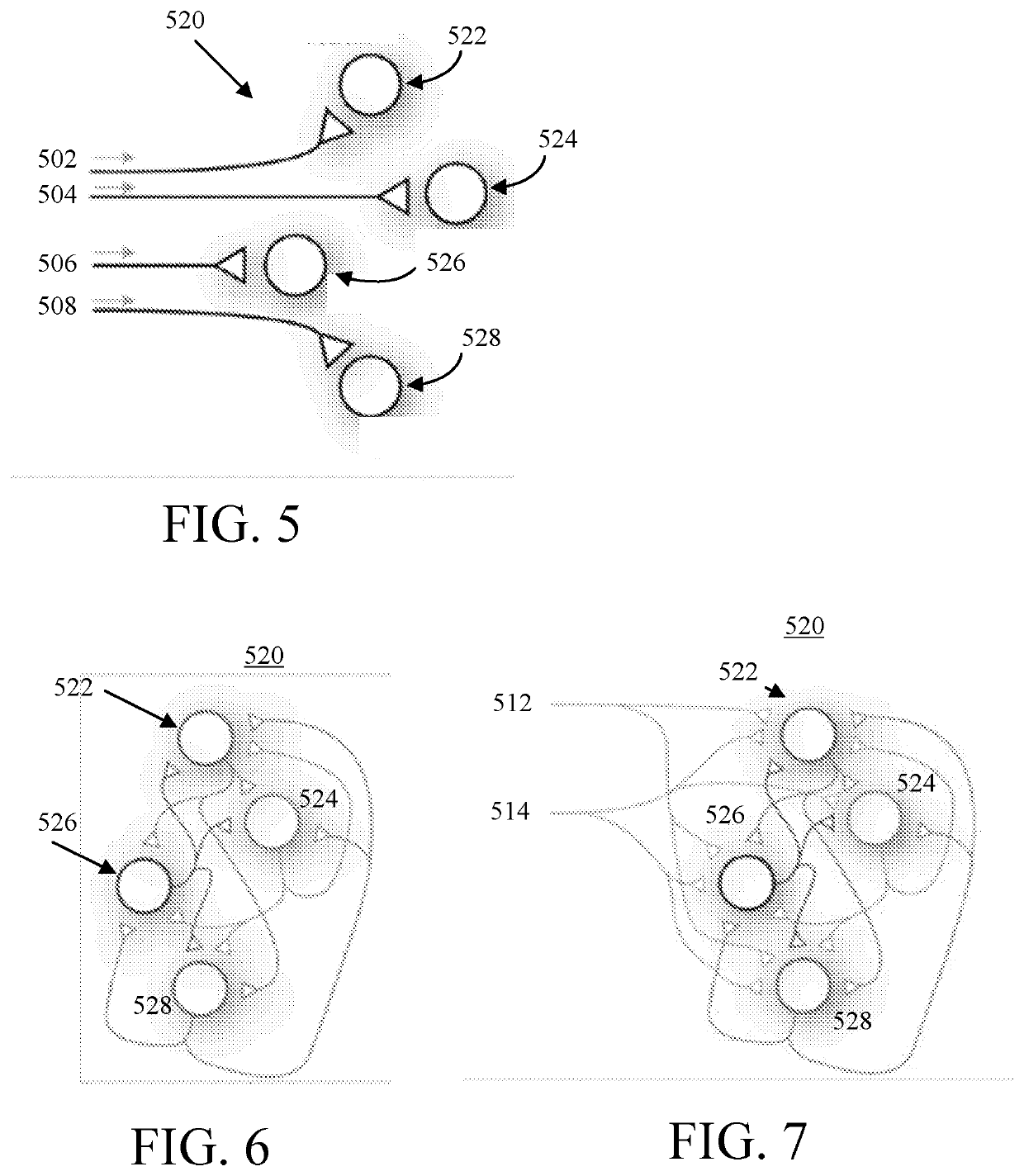
[0042]In the following, embodiments will be described where FIG. 1 is a flowchart illustrating example method steps according to an embodiment of the present disclosure. FIG. 1 shows a computer-implemented or hardware-implemented method 100 of entity identification. Thus, the method may be implemented in hardware, software, or any combination of the two. The method comprises providing 110 a network 520 (shown in FIG. 5) of nodes 522, 524, 526, 528 with input 502, 504, 506, 508 from a plurality of sensors. The network 520 may be a recurrent network, such as a recurrent neural network. The s...


PUM


Abstract

A computer-implemented or hardware-implemented method of entity identification, comprising: a) providing a network of nodes with input from a plurality of sensors; b) generating, by each node of the network, an activity level, based on the input from the plurality of sensors; c) comparing the activity level of each node to a threshold level; d) based on the comparing, for each node, setting the activity level to a preset value or keeping the generated activity level; e) calculating a total activity level as the sum of all activity levels of the nodes of the network; f) iterating a)-e) until a local minimum of the total activity level has been reached; and g) when the local minimum of the total activity level has been reached, utilizing a distribution of activity levels at the local minimum to identify a measurable characteristic of the entity. The disclosure further relates to a computer program product and an apparatus for entity identification.

Description

TECHNICAL FIELD[0001]The present disclosure relates to a computer-implemented or hardware-implemented method of entity identification, a computer program product and an apparatus for entity identification. More specifically, the disclosure relates to a computer-implemented or hardware-implemented method of entity identification, a computer program product and an apparatus for entity identification as defined in the introductory parts of claim 1, claim 9 and claim 10.BACKGROUND ART[0002]Entity identification is known from prior art. One technology utilized for performing entity identification is neural networks. One type of neural network that can be utilized for entity identification is the Hopfield network. A Hopfield network is a form of recurrent artificial neural network. Hopfield networks serve as content-addressable (“associative”) memory systems with binary threshold nodes.[0003]However, existing neural network solutions have poor performance and / or low reliability. Furthermo...

Claims


Application Information

Patent Timeline
Patent Type & Authority Applications(United States)
IPC IPC(8): G06N3/04
CPCG06N3/0481G06N3/044G06N3/048G06F3/04144G01L5/228G10L17/18G10L15/16H04N23/695G06N3/063G06N3/02
Inventor RONGALA, UDAYAJÖRNTELL, HENRIK
Owner INTUICELL AB
Learn More