Method and a system for generating an adaptive slicer threshold

a technology of slicer threshold and slicer, which is applied in the direction of amplitude demodulation, dc level restoring means or bias distort correction, baseband system details, etc., can solve the problems of low signal level, noise and/or jitter, adversely affecting the signal processing equipment to which the output of the receiver is applied, and the slicer threshold is sensitive to noise. , the effect of good noise insensitivity and less nois

Inactive Publication Date: 2011-12-06
ST ERICSSON SA
View PDF20 Cites 0 Cited by
  • Summary
  • Abstract
  • Description
  • Claims
  • Application Information

AI Technical Summary

Benefits of technology

[0010]Accordingly it is an object of the invention to provide a method of generating an adaptative slicer threshold with an improved noise insensibility.
[0014]In the above method, the slicer threshold is calculated from the average of several maximum values and several minimum values. Therefore, the slicer threshold is less sensitive to noise.
[0015]The features as defined in claim 2 have the advantage that the method obviates the need for a complicated leakage function.
[0016]The features as defined in claims 3 and 4 have the advantage that the method results in a good noise insensitivity as well as a fast time response to changes in the level of the binary signal to be sliced.
[0017]The features of claims 5 and 6 have the advantage that in case of long logic one or logic zero sequences in the binary signal, the slicer threshold value is not impacted.

Problems solved by technology

In many cases, the signals received are of a low level and are accompanied by noise and / or jitter.
The true binary nature of a distinct rectangular pulse, usually designating a binary one, sometimes can be partly obscured by noise, and results in data errors that adversely affect signal processing equipment to which the output of the receiver is applied.
Therefore, the slicer threshold is sensitive to noise, especially when the noise introduces large peaks in the received binary signal, which peaks will directly change the slicer threshold.

Method used


Image

  • Method and a system for generating an adaptive slicer threshold
  • Method and a system for generating an adaptive slicer threshold
  • Method and a system for generating an adaptive slicer threshold

Examples


Embodiment Construction

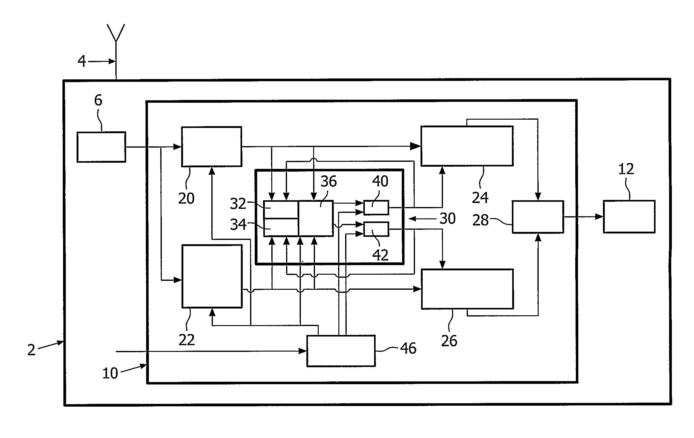
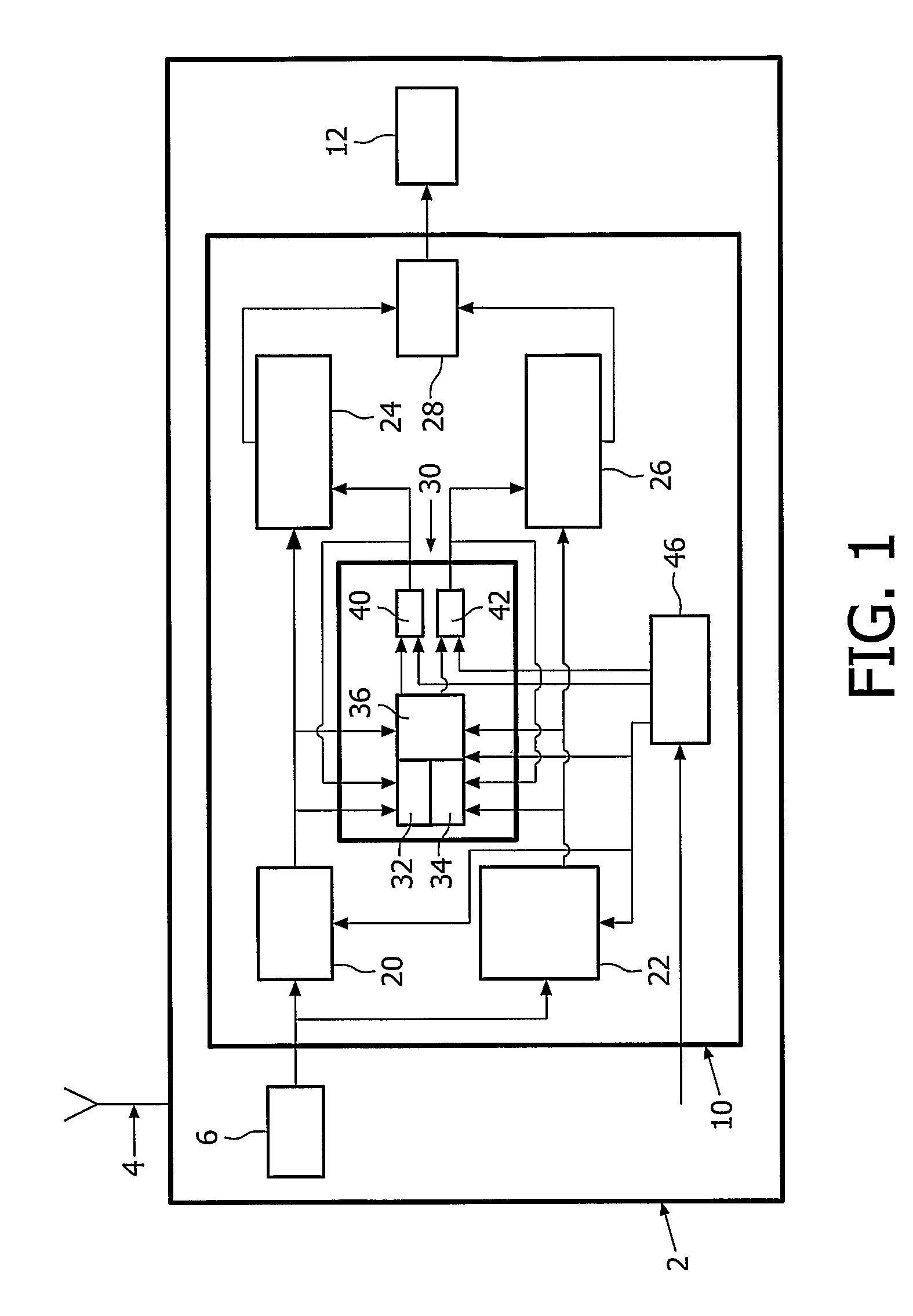
[0023]FIG. 1 shows a wireless receiver 2 intended to be used in a Bluetooth wireless communication system. Only the elements of receiver 2 that are necessary for the understanding of the invention are illustrated.

[0024]In order to receive a modulated radio signal, receiver 2 comprises an antenna 4, a demodulator 6 to demodulate the received radio signal, a circuit 10 to generate an adaptative slicer threshold, and a slicer circuit 12 capable of slicing a binary signal according to the slicer threshold generated by circuit 10.

[0025]Demodulator 6 is designed to convert the received modulated signal into a demodulated received signal applied to a first input of circuit 10. The demodulated signal is a binary signal that is a two-state signal separated by transitions to move from one state to the other.

[0026]A curve 16 of the graph of FIG. 3 represents the time evolution of an example of such a binary signal. The x-axis is graduated in micro-seconds and the y-axis represents the amplitud...


PUM


Abstract

An adaptive slicer threshold is derived from averages of maximum and minimum values of the received signal, the method comprising the steps of: —averaging (86) several detected maximum values and averaging several detected minimum values, and —calculating (86) the slicer threshold from these average minimum and maximum values.

Description

FIELD OF THE INVENTION[0001]The present invention relates to a method and a system of generating an adaptative slicer threshold.[0002]More precisely, the invention relates to a method of generating an adaptative slicer threshold, the method comprising the steps of:[0003]detecting a maximum value of the signal over a predetermined period for at least two periods, and[0004]detecting a minimum value of the signal over a predetermined period for at least two periods.[0005]Data communication using demodulated binary signals takes place at high rates in various applications, for example, in wireless systems like DECT (Digital European Cordless Telecommunication) or Bluetooth. In such binary data communication systems, a receiver is used for receiving the binary signals from a transmitter. In many cases, the signals received are of a low level and are accompanied by noise and / or jitter. The true binary nature of a distinct rectangular pulse, usually designating a binary one, sometimes can ...

Claims


Application Information

Patent Timeline
Patent Type & Authority Patents(United States)
IPC IPC(8): H03H7/30H03H7/40H03K5/159H04L25/06
CPCH04L25/062H04L25/06
Inventor VAN DER TUIJN, ROLAND MATTHEUS MARIA HENDRICUSBOUVET, YOANN
Owner ST ERICSSON SA
Why Eureka
Try Eureka