
Hibernation solution for embedded devices and systems

a technology of embedded devices and systems, applied in the field of embedded systems, can solve the problems of low consumption, power consumption in order to maintain data, and non-zero

Inactive Publication Date: 2011-05-05
CSR TECH HLDG
View PDF8 Cites 30 Cited by
  • Summary
  • Abstract
  • Description
  • Claims
  • Application Information

AI Technical Summary

Benefits of technology

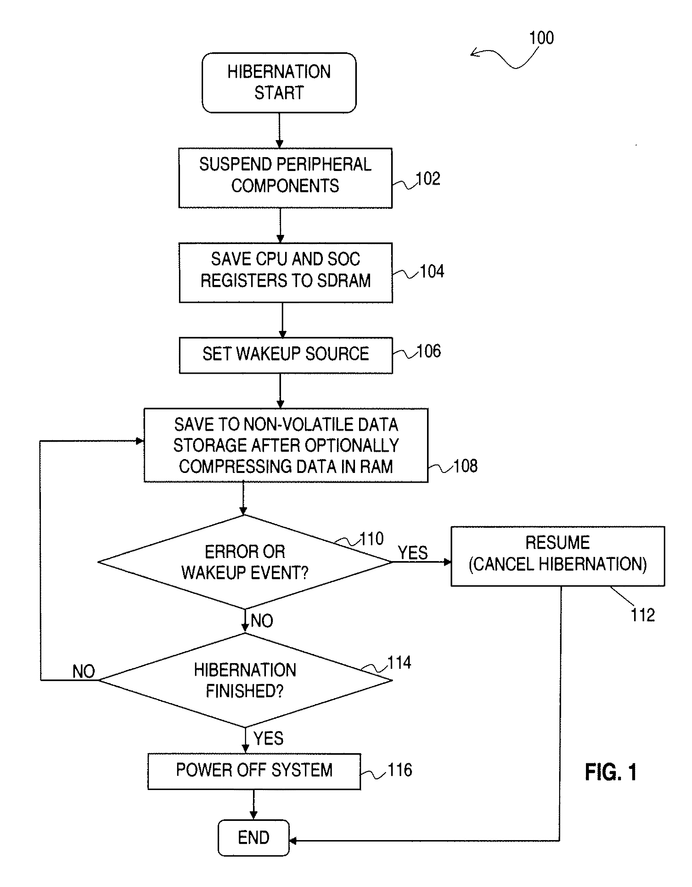
[0011]According to an aspect of the present invention, an embedded device is hibernated by storing CPU and SOC data in the RAM of the embedded device, storing the RAM data to a non-volatile data storage medium, and powering off the embedded device. In furtherance of this aspect, the embedded device is later woken up in response to the detection of a wakeup event from a wakeup source. In furtherance of these and other aspects, the data stored in the RAM of the embedded device comprises one or more registers of a Central Processing Unit (CPU) of the embedded device, and one or more registers or of a system-on-chip (SOC) of the embedded device. According to further aspects of the invention, the CPU and SOC data includes information that is useful for performing a GPS navigation process.

Problems solved by technology

In sleep or sleep state, however, data is stored on the SDRAM of the embedded device, and power is consumed in order to maintain the data stored on the SDRAM.
Although this power consumption is low, it is nevertheless non-zero, and power consumption is especially evident if the SDRAM is a DDR2 SDRAM.
In addition, because of the non-zero power consumption by the SDRAM, eventually battery may run out of power.
When the battery runs out of power, the content of the SDRAM will no longer be maintained, and user data may be lost.
However, there is no good support for hibernation in current embedded systems.
This information is typically lost when the internal memory of a GPS system loses power and cannot be refreshed.
So when the system power is restored, this information needs to be accumulated all over again, which takes substantial time.

Method used


Image

  • Hibernation solution for embedded devices and systems
  • Hibernation solution for embedded devices and systems
  • Hibernation solution for embedded devices and systems

Examples


Embodiment Construction

[0020]The present invention will now be described in detail with reference to the drawings, which are provided as illustrative examples of the invention so as to enable those skilled in the art to practice the invention. Notably, the figures and examples below are not meant to limit the scope of the present invention to a single embodiment, but other embodiments are possible by way of interchange of some or all of the described or illustrated elements. Moreover, where certain elements of the present invention can be partially or fully implemented using known components, only those portions of such known components that are necessary for an understanding of the present invention will be described, and detailed descriptions of other portions of such known components will be omitted so as not to obscure the invention. In the present specification, an embodiment showing a singular component should not be considered limiting; rather, the invention is intended to encompass other embodimen...


PUM


Abstract

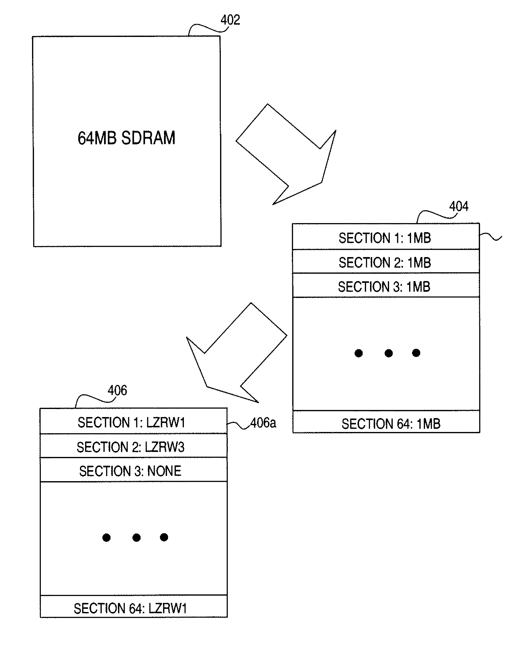
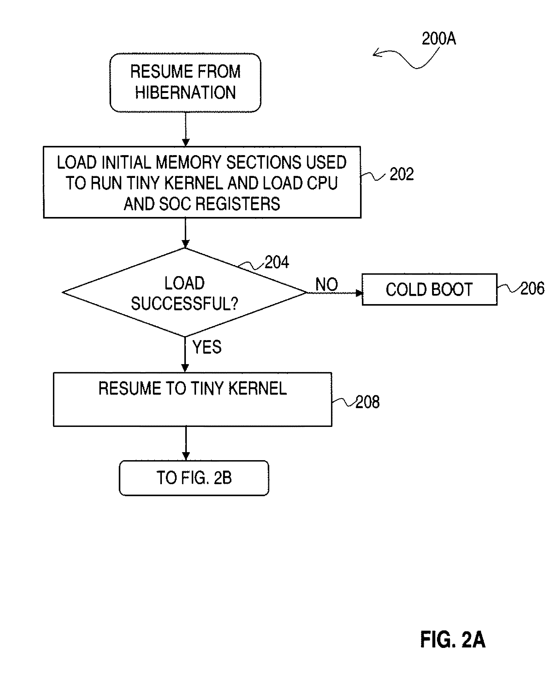
An embedded device is hibernated by storing state data of the embedded device to a non-volatile data storage medium, and powering off the embedded device. The embedded device is later woken up in response to the detection of a wakeup event from a wakeup source. The state data stored in the RAM of the embedded device comprises data in one or more registers of a Central Processing Unit (CPU) of the embedded device, one or more registers of a system-on-chip (SOC) of the embedded device, and the system and applications code and data. Waking the embedded device comprises loading, from the non-volatile data storage medium, initial memory sections that are used to run a kernel of the embedded device. State data that is stored in the RAM of a system may be compressed by dividing the RAM into a plurality of sections and independently choosing, for each section in the plurality of sections, a corresponding compression arithmetic.

Description

FIELD OF THE INVENTION[0001]The present invention is related to embedded systems, and more particularly, to a method and apparatus for hibernation of an embedded system.BACKGROUND OF THE INVENTION[0002]Performance and power consumption are key elements for embedded devices, or embedded systems. Currently, embedded devices enter a sleep or deep sleep state in response to users' pressing of power buttons to switch off the embedded devices. In sleep or sleep state, however, data is stored on the SDRAM of the embedded device, and power is consumed in order to maintain the data stored on the SDRAM. Although this power consumption is low, it is nevertheless non-zero, and power consumption is especially evident if the SDRAM is a DDR2 SDRAM.[0003]In addition, because of the non-zero power consumption by the SDRAM, eventually battery may run out of power. When the battery runs out of power, the content of the SDRAM will no longer be maintained, and user data may be lost.[0004]Hibernation mod...

Claims


Application Information

Patent Timeline
Patent Type & Authority Applications(United States)
IPC IPC(8): G06F12/06G06F11/20
CPCG01S19/34Y02B60/186G06F9/4418G06F1/3203Y02D10/00
Inventor DUAN, BINGHUA
Owner CSR TECH HLDG
Learn More