Integrated Vacuum Wand and Method of Use
- Summary
- Abstract
- Description
- Claims
- Application Information
AI Technical Summary
Benefits of technology
Problems solved by technology
Method used
Image

Examples
first embodiment
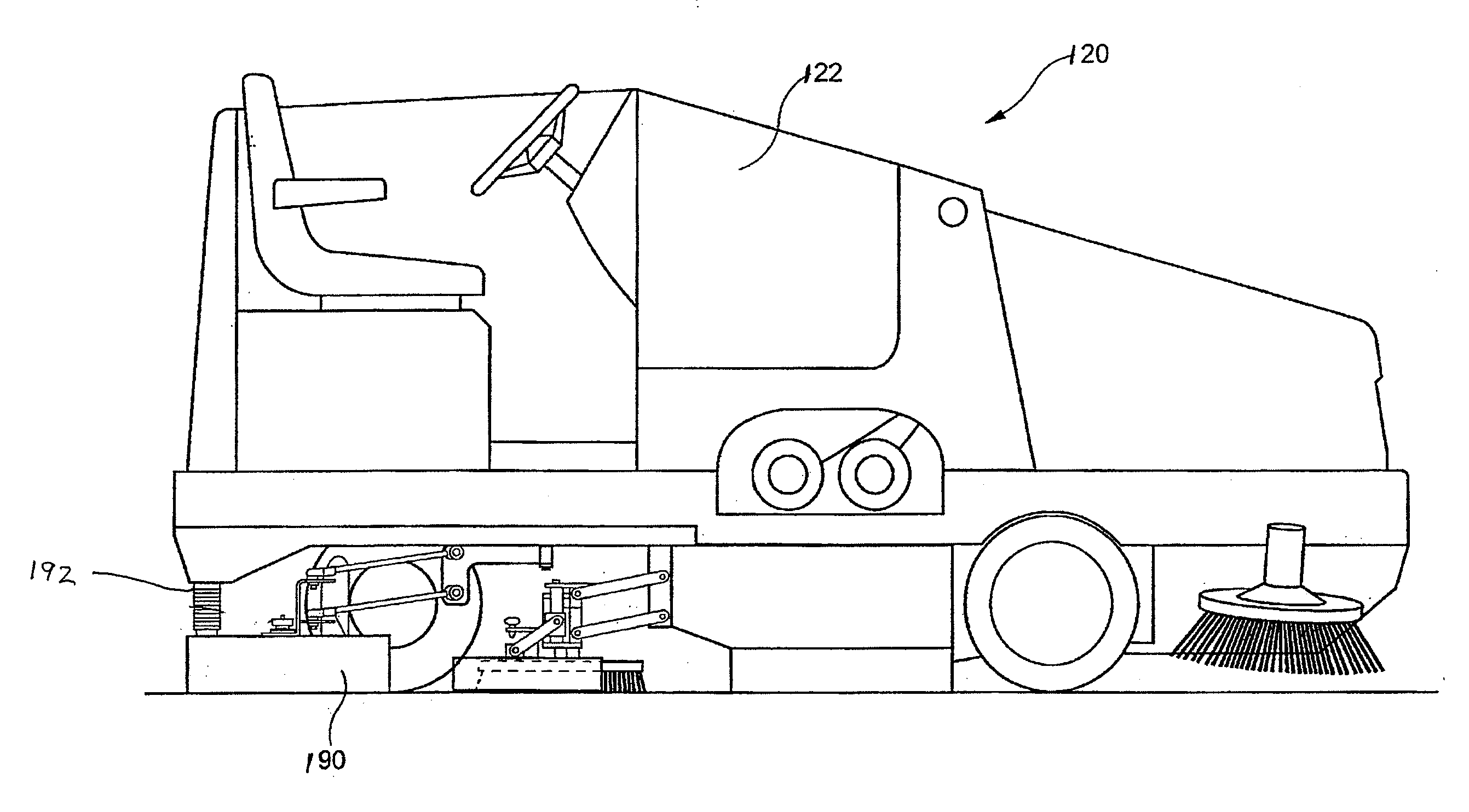
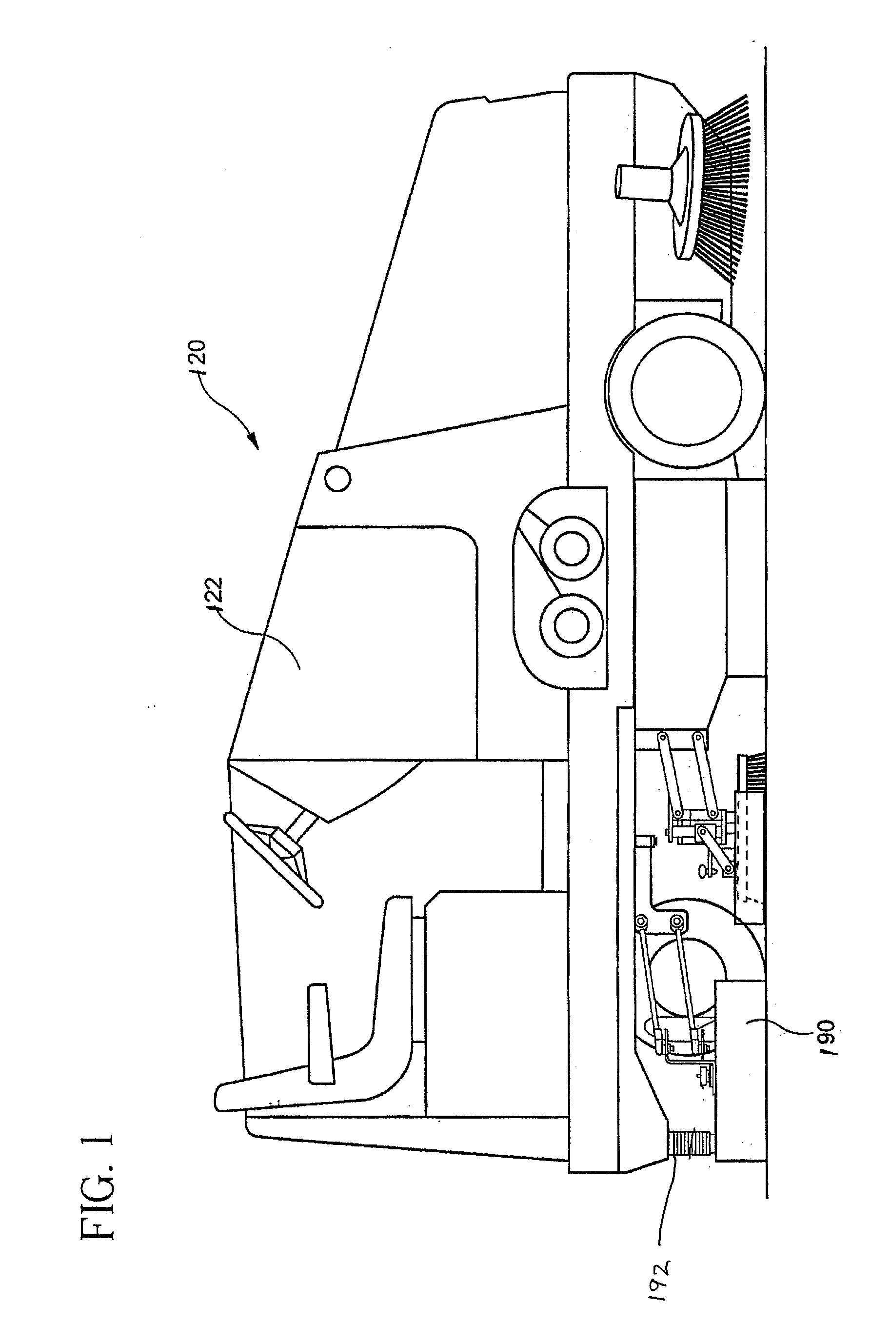
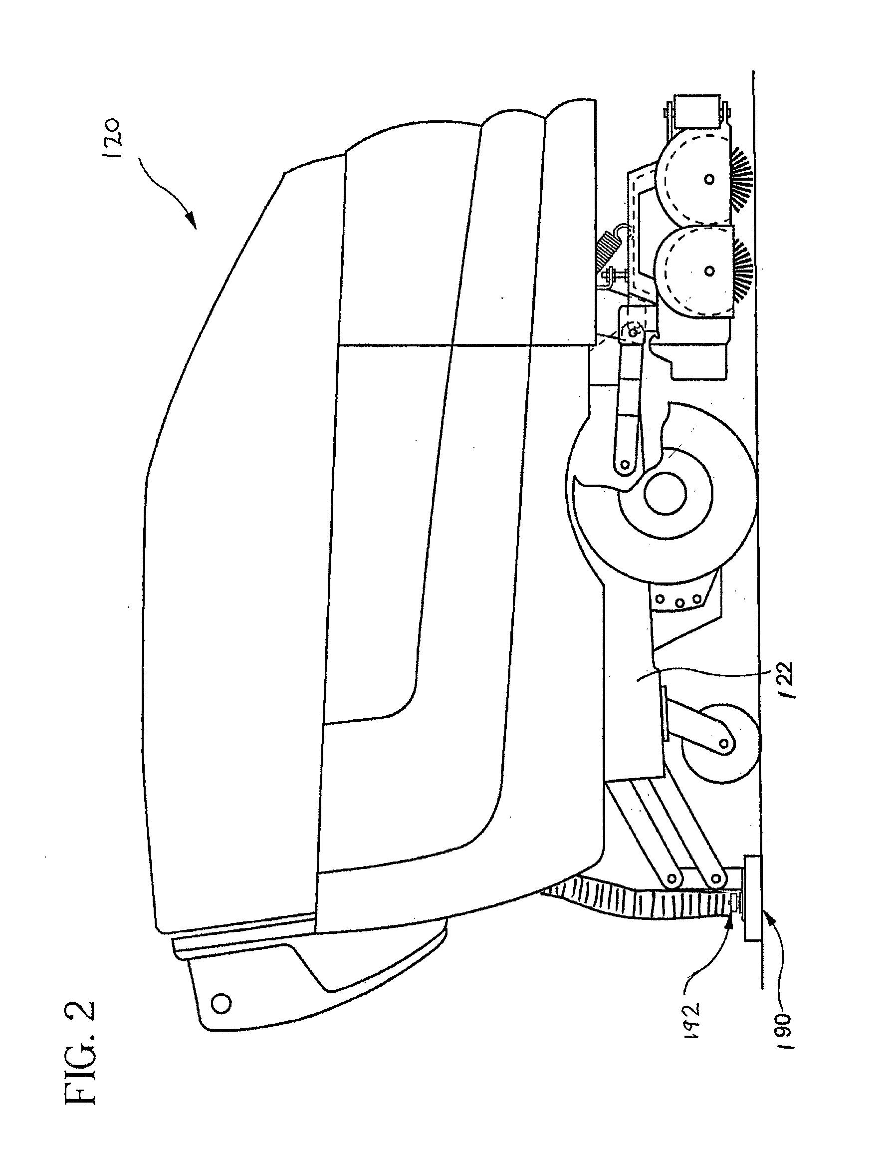
[0028]Referring now to FIG. 3-16, wand assembly 24 of the present invention includes a wand head 40 connected to a tubular, telescoping handle 42. The wand head 40 is coupled to flexible, collapsible vacuum hose 26. As described hereinafter, wand head 40 is adapted to be removed from rear squeegee assembly 28 to allow for remote debris pickup. Vacuum hose 26 remains coupled to wand head 40 and extends in length during remote debris pickup. When the wand is not in use, as shown in FIG. 3, the vacuum hose 26 provides the vacuum to the rear squeegee assembly 28 via adapter 29. The opposite end of vacuum hose 26 is operatively coupled to a vacuum fan which will supply vacuum to the hose 26.
[0029]A debris collection vehicle may be a wet floor scrubbing machine having cleaning liquid dispensing systems, scrubbing pads, and a rear squeegee assembly 28. Squeegee assembly 28 includes a front squeegee blade 32 and a rear squeegee blade 34. Additional aspects of rear squeegee assembly 28 are d...
second embodiment
[0042]Referring now to FIG. 17, a wand assembly 224 of the present invention is shown. Wand assembly 224 includes a wand head 240 connected to a tubular, telescoping handle 242 in fluid communication with a cleaning solution source to dispense cleaning solution from nozzle 244 (shown in FIG. 19). Wand head 240 is also connected to vacuum line 226 in communication with a vacuum source. Wand head 240 includes a scrub pad 246 (shown in FIG. 19) used during remote cleaning. Wand head 240 is operative coupled to rear squeegee assembly 228 to communicate a vacuum to rear squeegee assembly 228 to remove debris and soiled cleaning solution from a floor surface.
[0043]The wand head 240 is coupled to flexible, collapsible vacuum hose 226. FIG. 17 shows the stored or captured position of wand assembly 224. When stretched to its full extent by the operator's removal of the wand from the vehicle, the hose may permit the operator to collect debris at a distance as great as 15 feet from the cleanin...
PUM
 Abstract
Description
Claims
Application Information
 - Generate Ideas
- Intellectual Property
- Life Sciences
- Materials
- Tech Scout
- Unparalleled Data Quality
- Higher Quality Content
- 60% Fewer Hallucinations
Browse by: Latest US Patents, China's latest patents, Technical Efficacy Thesaurus, Application Domain, Technology Topic, Popular Technical Reports.
© 2025 PatSnap. All rights reserved.Legal|Privacy policy|Modern Slavery Act Transparency Statement|Sitemap|About US| Contact US: help@patsnap.com