Pneumatic tire

a technology of pneumatic tires and side portions, applied in the field of pneumatic tires, can solve problems such as heat generation over tires, and achieve the effects of suppressing a rise in a temperature of side portions, excellent durability, and suppressing damag

Inactive Publication Date: 2011-05-12
SUMITOMO RUBBER IND LTD
View PDF4 Cites 11 Cited by
  • Summary
  • Abstract
  • Description
  • Claims
  • Application Information

AI Technical Summary

Benefits of technology

[0013]In the tire, the agitating portion including a large number of dimples is provided on the external surface of the side portion. The agitating portion can agitate air which is present around the running tir

Problems solved by technology

The repetition of the deformation and the restor

Method used


Image

  • Pneumatic tire
  • Pneumatic tire
  • Pneumatic tire

Examples


example 1

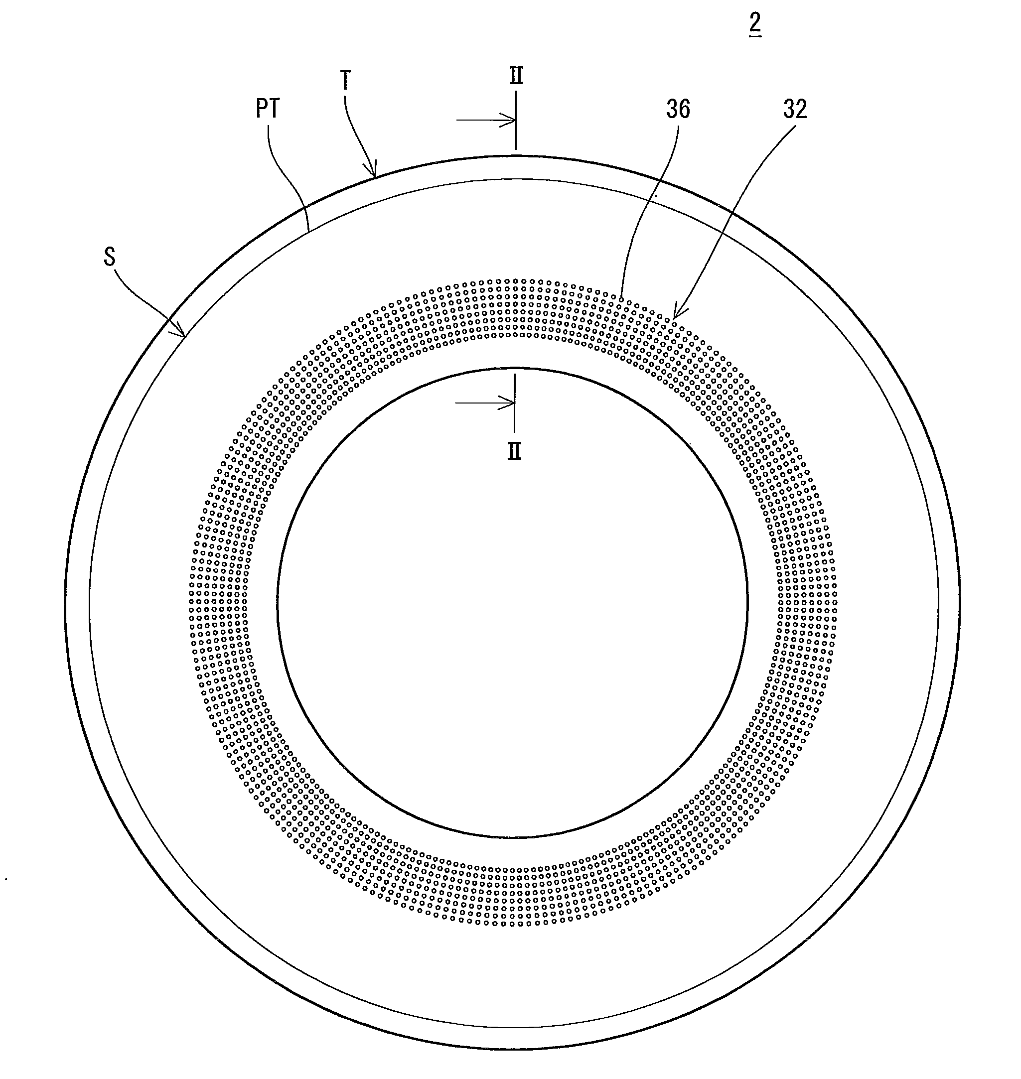
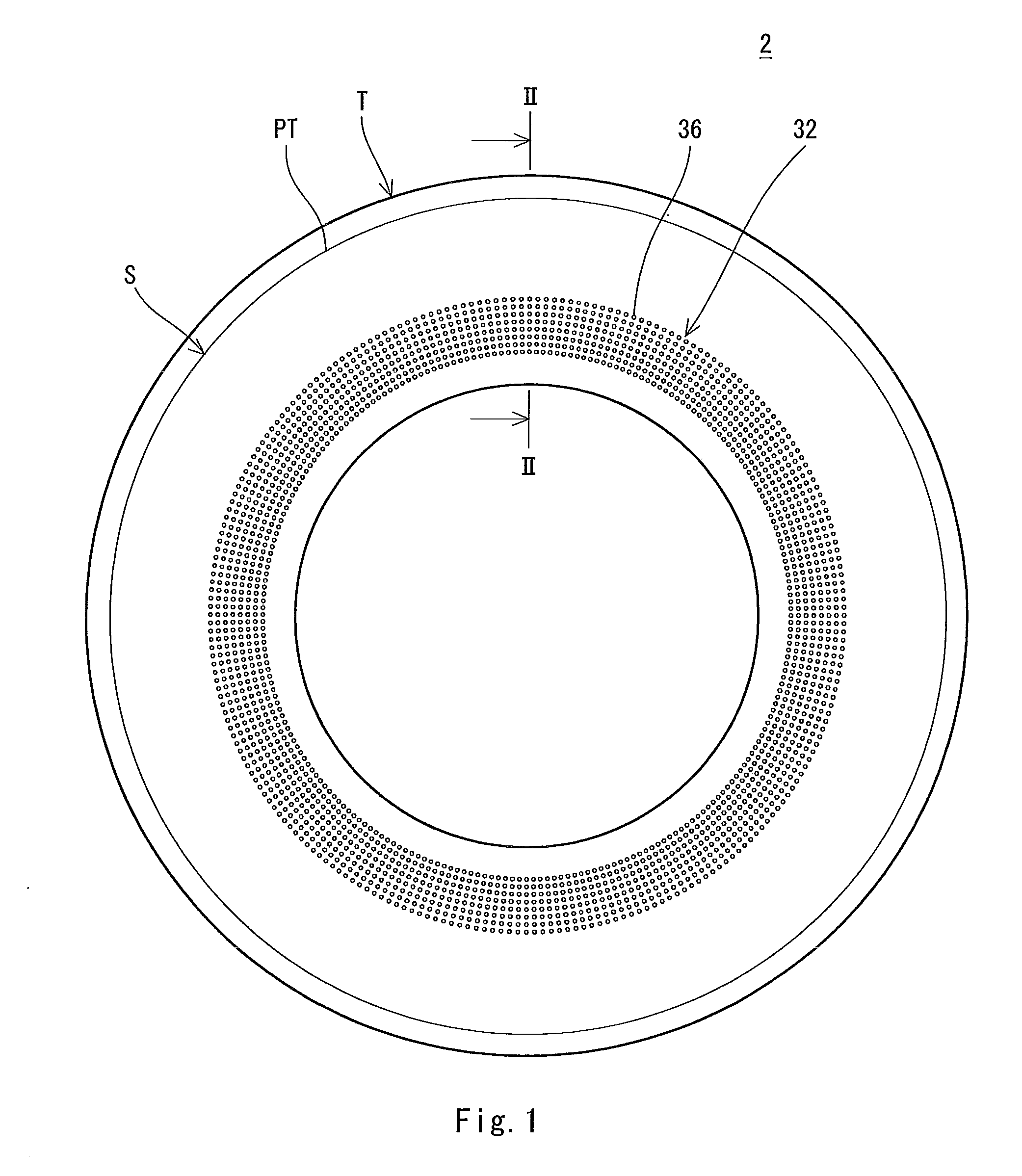
[0099]There was obtained a tire for a passenger car according to an example 1 which has the basic structure shown in FIG. 1 and a specification shown in the following Table 2. The tire has a size of 195 / 65R15. The tire includes the agitating portion shown in FIG. 3. The agitating portion is provided with a large number of dimples. The dimples have an array pattern of an orthogonal array. The agitating portion does not include a pimple. The dimple has an outside diameter R1 of 4 mm. A ratio (D / R1) of a depth D of the dimple to the outside diameter R1 is 0.45. A ratio (L / R1) of a distance L between a center of one of the dimples and a center of the other dimple which is close to the one of the dimples to the outside diameter R1 is 1.5.

example 17

[0103]A tire was obtained in the same manner as in the example 1 except that an agitating portion has the structure shown in FIG. 5. The agitating portion includes a large number of dimples and pimples to be the agitators. An array pattern of the dimples and the pimples is an orthogonal array. The dimples and the pimples are arranged alternately. The dimple has an outside diameter R1 of 4 mm. A ratio (D / R1) of a depth D of the dimple to the outside diameter R1 is 0.4. A ratio (L / R1) of a distance L between centers of the agitators to the outside diameter R1 is 1.5. The pimple has an outside diameter R2 of 4 mm. A ratio (H / R2) of a height H of the pimple to the outside diameter R2 is 0.4. A ratio (L / R2) of the distance L between the centers of the agitators to the outside diameter R2 is 1.5. A ratio of a total number Nd of the dimples to a total number Np of the pimples is one. A ratio of a number Nd4 of the dimples to which four pimples are close respectively to the total number Nd ...

example 18

[0104]A tire was obtained in the same manner as in the example 1 except that an agitating portion is set to have the structure shown in FIG. 7. The agitating portion includes a large number of dimples and pimples. An array pattern of the dimples and the pimples is a zigzag array. The dimples and the pimples are arranged alternately. The dimple has an outside diameter R1 of 4 mm. A ratio (D / R1) of a depth D of the dimple to the outside diameter R1 is 0.4. A ratio (L / R1) of a distance L between centers of agitators to the outside diameter R1 is 1.5. The pimple has an outside diameter R2 of 4 mm. A ratio (H / R2) of a height H of the pimple to the outside diameter R2 is 0.4. A ratio (L / R2) of the distance L between the centers of the agitators to the outside diameter R2 is 1.5. A ratio of a total number Nd of the dimples to a total number Np of the pimples is 0.5. A ratio of a number Nd6 of the dimples to which six pimples are close respectively to the total number Nd of the dimples is o...


PUM


Abstract

A tire (2) includes a tread portion (T) and a pair of side portions (S). An agitating portion (32) is provided on an inner part in a radial direction with respect to a position (PA) indicative of a maximum width over an external surface (34) of each of the side portions (S). The agitating portion (32) includes a large number of dimples (36) which are dented inward from the external surface. An edge of the dimple (36) has a circular contour. A ratio of a depth of the dimple (36) to an outside diameter of the dimple (36) is equal to or higher than 0.2 and is equal to or lower than 0.5. A ratio of a distance between a center of one of the dimples (36) and a center of the other dimple (36) which is close to the one of the dimples 36 to the outside diameter is equal to or higher than 1.2 and is equal to or lower than 2. It is preferable that the outside diameter of the dimple (36) should be equal to or greater than 3 mm and be equal to or smaller than 5 mm in the tire (482). It is preferable that an array pattern of the large number of dimples (36) should be an orthogonal array in the tire (2).

Description

TECHNICAL FIELD[0001]The present invention relates to a pneumatic tire.BACKGROUND ART[0002]A running tire supports a vehicle body while carrying out a rotation. In the tire, a deformation and a restoration are repeated alternately. The repetition of the deformation and the restoration causes a generation of heat over the tire.[0003]In respect of the fact that a vehicle can run continuously by a certain distance at a high speed in a puncture, a run flat tire having a reinforcing rubber layer provided in a sidewall portion is disclosed in Japanese Laid-Open Patent Publication No. 2007-50854. In the sidewall portion of the run flat tire, there is provided a plurality of radiating groove-shaped portions which can effectively dissipate heat stored in the reinforcing rubber layer in a running operation in a puncture state.[0004]Patent Document 1: Japanese Laid-Open Patent Publication No. 2007-50854DISCLOSURE OF THE INVENTIONProblems that the Invention is to Solve[0005]In a running tire, a...

Claims


Application Information

Patent Timeline
IPC IPC(8): B60C23/19
CPCB60C13/02B60C13/00B60C5/12B60C23/18
Inventor TAKAHASHI, MASANORI
Owner SUMITOMO RUBBER IND LTD
Why Eureka
Try Eureka