This helps you quickly interpret patents by identifying the three key elements:
Problems solved by technology
Method used
Benefits of technology
[0012]The above and other objects and advantages are attained in accordance with the present invention by providing a pouch having magnets affixed to the interior lining of the pouch's upper and lower panels. Due to the magnetic polarity of each magnet being equally directed, mating profile pouches can be attached to another mating profile pouch through the magnetic pull
Problems solved by technology
In general these bags were distinctively designed for each article category's specifications, which resulted in a style that restricted the use, design, and storage capacity of the bag.
This was found to be inconvenient and limiting for the user since it prevented the flexibility to cust
Method used
Image
Click on the blue label to locate the original text in one second.
Reading with bidirectional positioning of images and text.
Examples
Embodiment Construction
[0020]While the invention will be described in connection with a preferred embodiment, it will be understood that it is not intended to limit the invention to this embodiment. On the contrary, it is intended to cover all alternatives, modifications and equivalents as may be included within the spirit and scope of the invention as defined by the appended claims.
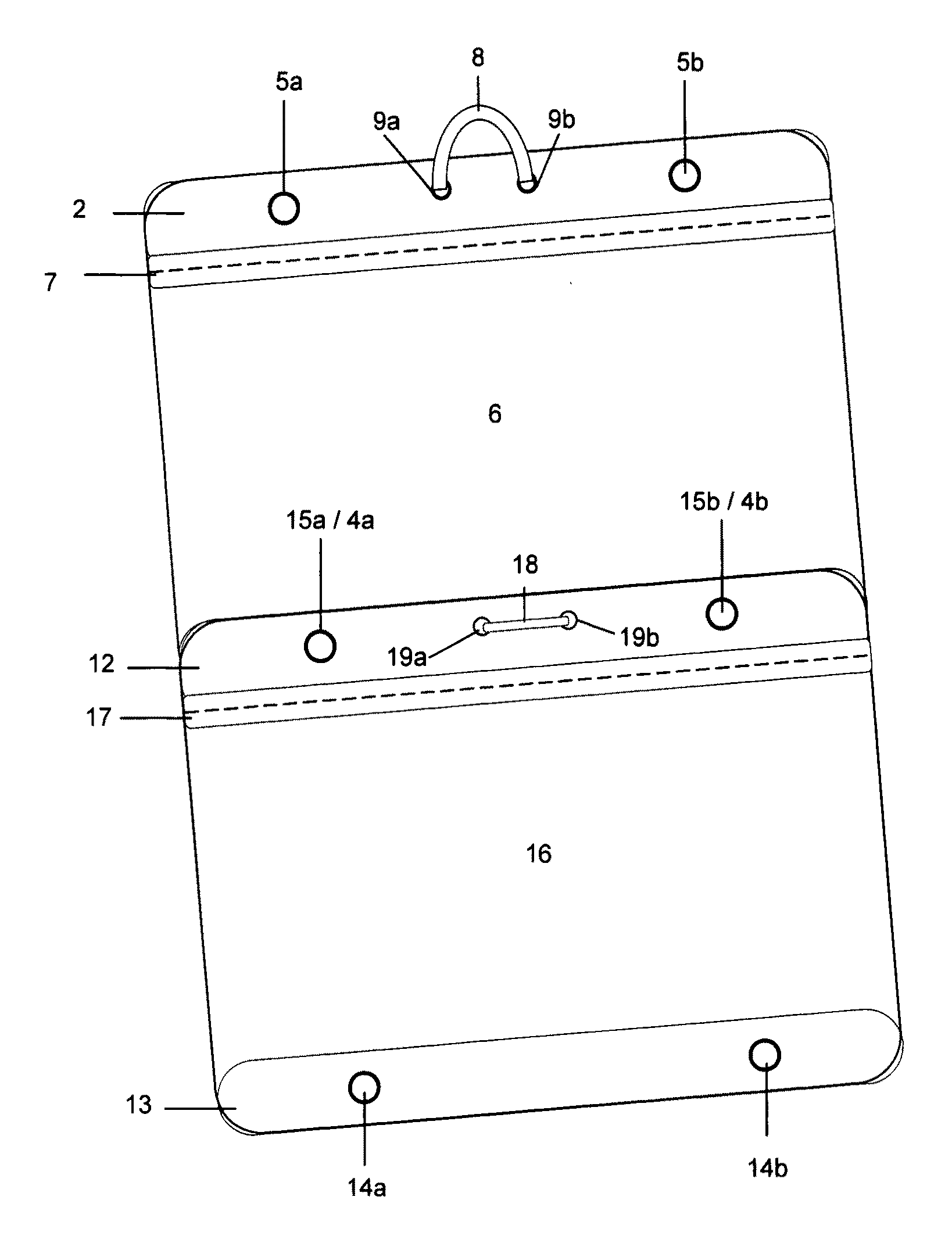
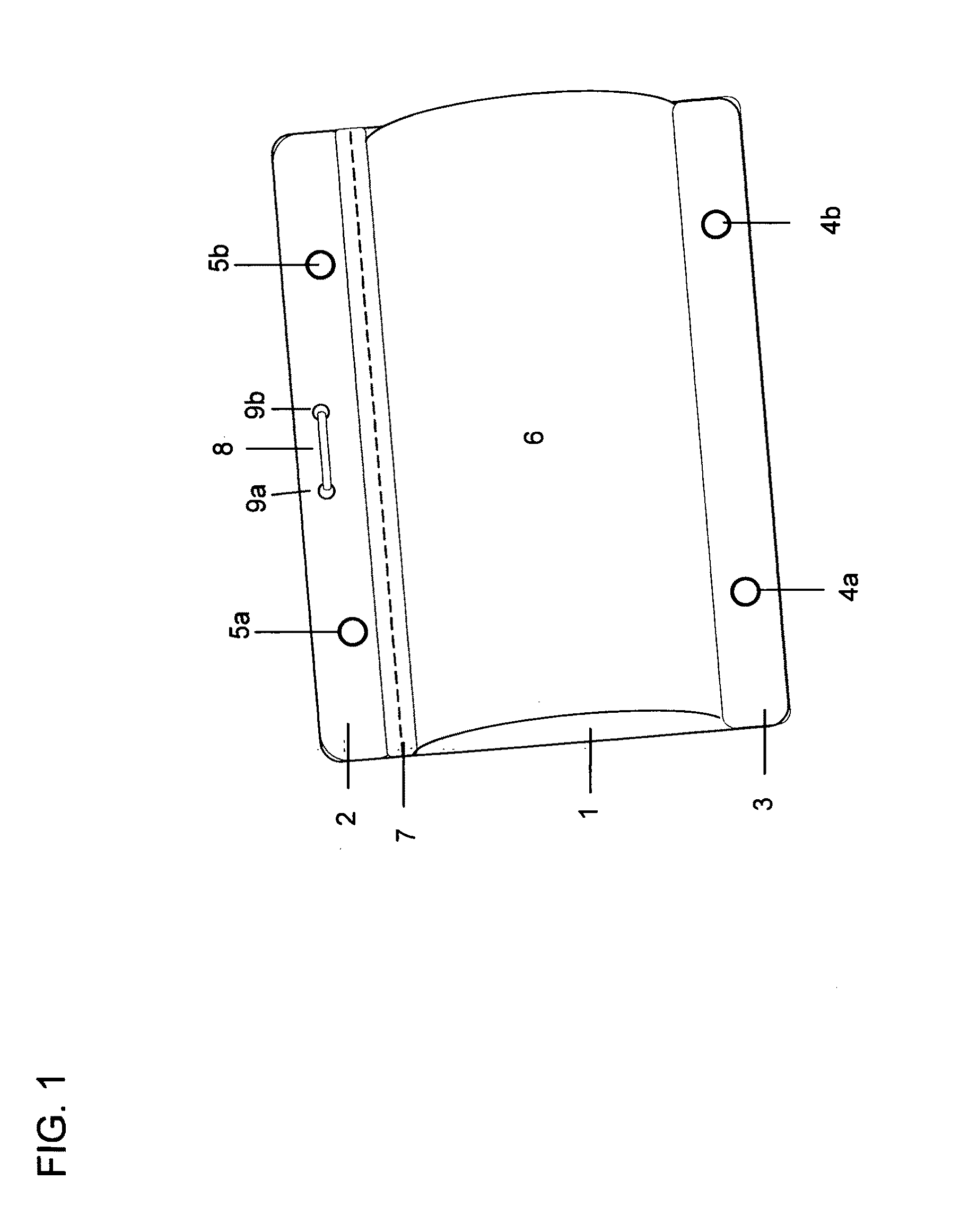
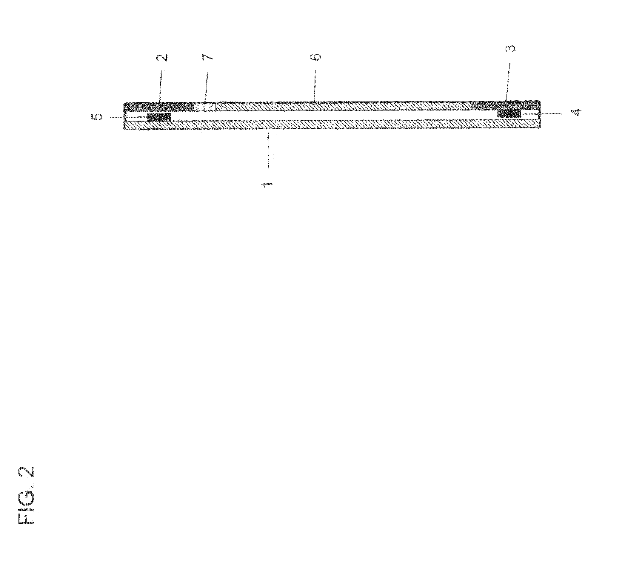
[0021]Reference is now made to FIG. 1, there is shown the magnetic pouch arranged and fitted in accordance with the present invention. It will be understood that the magnetic pouch can take any convenient shape, can be made of any combination of suitable flexible or rigid outer materials, and can be provided within a suitably attractive outer appearance. For example, the pouch can have a rigid plastic back exterior and clear vinyl sheet front exterior for additional durability and support.
[0022]The magnetic pouch illustrated in FIG. 1 wherein a pouch formed of fabric, sheet vinyl or any combination of both materials and utiliz...
PUM
Abstract
A zipper pouch—that can be of any size—featuring magnets that are embedded within the interior lining of the pouch. The polarity direction of each magnet is equal on the pouch, thereby facilitating the attachment of mating profile pouches. This synthesized magnetic polarity enables multiple connection configurations of mating profile pouches: the attachment of one mating profile pouch directly on top of another mating profile pouch, and the attachment of a mating profile pouch's upper panel to the lower panel of another mating pouch. The magnets are positioned to each upper and lower panel and equal in number and positioning per pouch; however, the total number of magnets per pouch can vary, depending upon the scale and weight capacity requirements of the pouch. The illustration shows the established mirror positioning of the magnets along the top and lower panels of the pouch. The upper magnets are adhered to and placed in-between the pouch's back interior lining and modesty fabric panel. The lower magnets are adhered to and placed in-between the pouch's lower front panel and modesty fabric panel. Each modesty fabric panel conceals the magnet from the pouch's interior view.
Description
REFERENCES SITED[0001]U.S. PATENT DOCUMENTS20030071095Apr. 17, 2003Dedrick, Ted R.224 / 6810090261600Oct. 22, 2009D'ambrosio, Carlo 292 / 251.54,480,361Nov. 06, 1984Morita, Tamao 24 / 3034,453,294Jun. 12, 1984Morita, Tamao 24 / 30320060029298Feb. 09, 2006Arends, Craig383 / 37 7,264,119Sep. 04, 2007Navickas, Jonas A.206 / 390BACKGROUND OF THE INVENTION[0002]The present invention relates to organizational storage (for travel, garment and grooming products) making it easier to meet each end-user's unique requirements.[0003]Traditional storage bags and pouches used for travel and home (including garment, personal grooming product, cosmetics and jewelry bags) offered a wide variety of shapes, styles, and internal arrangements. In general these bags were distinctively designed for each article category's specifications, which resulted in a style that restricted the use, design, and storage capacity of the bag. This was found to be inconvenient and limiting for the user since it prevented the flexibil...
Claims
Application Information
Patent Timeline
Application Date:The date an application was filed.
Publication Date:The date a patent or application was officially published.
First Publication Date:The earliest publication date of a patent with the same application number.
Issue Date:Publication date of the patent grant document.
PCT Entry Date:The Entry date of PCT National Phase.
Estimated Expiry Date:The statutory expiry date of a patent right according to the Patent Law, and it is the longest term of protection that the patent right can achieve without the termination of the patent right due to other reasons(Term extension factor has been taken into account ).
Invalid Date:Actual expiry date is based on effective date or publication date of legal transaction data of invalid patent.